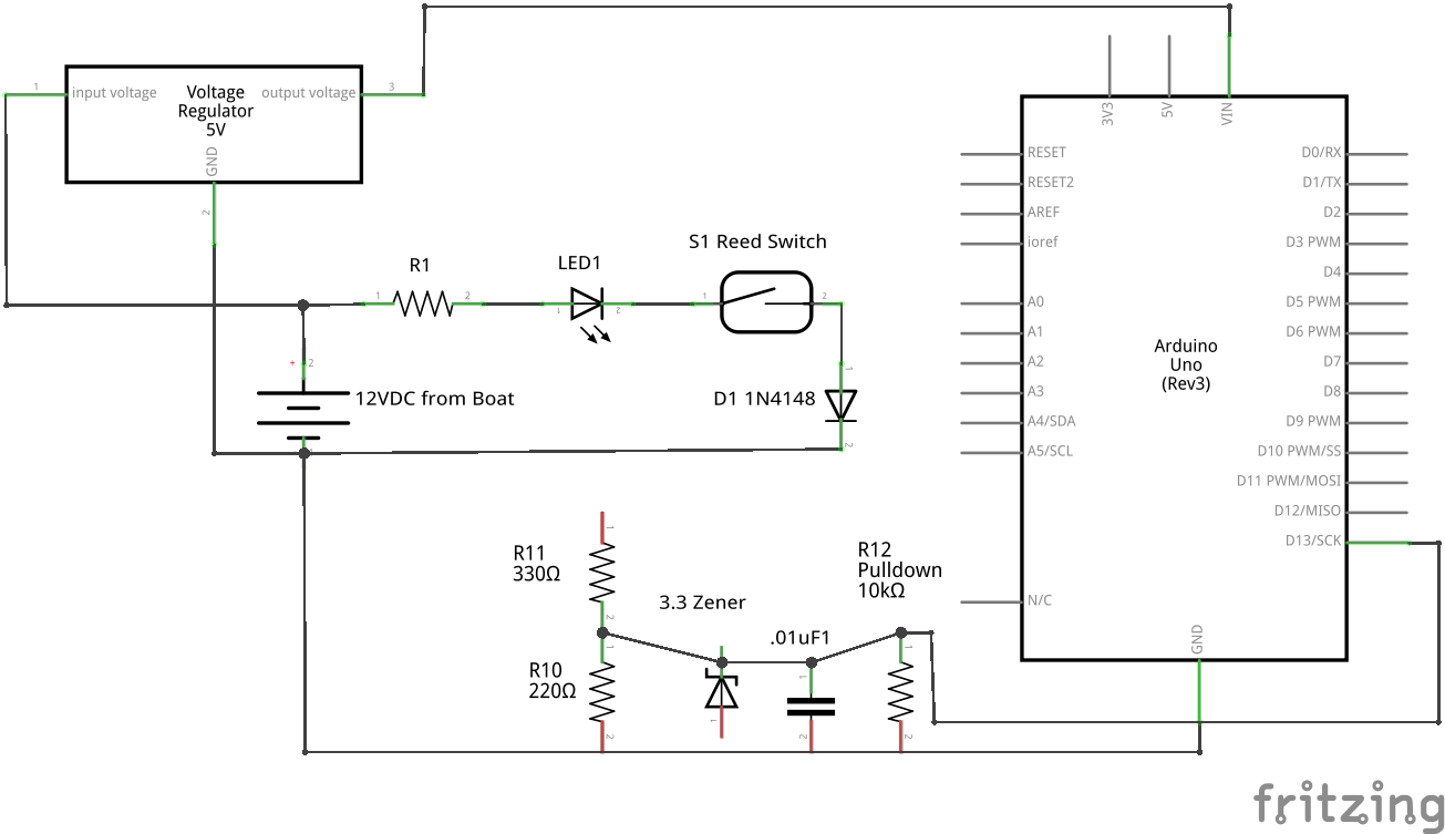
Attached is a schematic of a tank level sensor system that's installed on my boat, and the microcontroller I want to use to alert me when the tank is full. Everything is powered by the boat's 12V battery bank, which varies from 12.0V to about 14.6V.
I want to know when the float switch closes by monitoring with digitalRead() on a GPIO pin (or with an interrupt - how I do that isn't my problem). My problem is that I can't figure out where in the boat's existing tank level sensor system I can "tap into" a wire to provide the HIGH signal that will go into the GPIO pin. The existing sytem is in the left center of the image: the battery, R1, LED1, S1 and D1. I don't have physical access to the system from the battery to the LED (that's all inside the "black box"), but I do have access to the wire just before S1, then all the way back to the battery's GND.
The components at the bottom are all for stepping down the 12 - 14V to 3.3V that the GPIO pin needs: R11 and R10 (a voltage divider), the 3.3 Zener diode, the capacitor, and the pull-down resistor.
Is there a point in this circuit that I can "tap into" an existing wire to provide a 12V signal to go into R11? If so, I can't see where:
the wire just before S1 will always have 12 - 14V, regardless of the status of S1, so the pin would always be HIGH.
the wire just after S1 and before D1 is 0V when the switch is open (as expected), but only about 0.7V when the switch is closed. This is actually my problem - I thought that would be 12 - 14V, or at least something very close to that, but it's only about 0.7V.
If my approach is totally wrong, that's fine - please suggest an approach that will work. Thanks so much!
DrDiettrich:
Your observation is correct, you measure either 0V (no current) or the D1 diode forward voltage of 0.7V.
As a simple solution cut that wire and insert an opto coupler, whose output connects neatly to an Arduino input.
Actually, I measured again, and it's really 0.95V, and the Fwd Voltage of the 1N4148 is listed as 1V in the datasheet, so I guess that makes sense: the voltage drop from the anode to the cathode is the voltage that's "lost" in the process of forcing its way through the diode, right? (Yes, I'm very new to all things electronic.)
If that's the case, and that spot in the circuit will always be about 0.95V when the switch is closed, I think I can just use that as the input to my GPIO pin. The datasheet for it says the voltage for a pin to output HIGH is between 0.75 and 3.6. (It's an ESP8285, not an Arduino like in the schematic.) That sound right?
If I used an optocoupler at that spot, would 0.95V be enough to trigger it? The only one I have in my box is this one, and its datasheet says it needs between 0.75 and 1.5V, depending on the Forward Current - which I have no idea how to calculate. https://www.onsemi.com/pub/Collateral/H11L3M-D.pdf
Another option is to eliminate D1 and reverse the order of the other components: from battery positive, have switch, LED, R1 to battery negative (GND).
Then you can measure the voltage across R1, which will be the battery voltage minus the LED voltage. R1 can also be a voltage divider, for a range of output voltages.
jremington:
Another option is to eliminate D1 and reverse the order of the other components: from battery positive, have switch, LED, R1 to battery negative (GND).
Then you can measure the voltage across R1, which will be the battery voltage minus the LED voltage. R1 can also be a voltage divider, for a range of output voltages.
Except that, as noted in the original post, I don't have access to LED1 and R1, because they're inside the "black box" of the installed tank monitor.
DrDiettrich:
Don't rely on a fixed diode forward voltage. Insert the optocoupler LED into the line, not in parallel.
Two questions. Why NOT rely on the diode's forward voltage? Do you think it may not reliably be enough, or is there some other aspect that's unreliable?
I do have an H11L1M optocoupler. You're saying to put the anode and cathode of it in-line between S1 and D1?
Place it in series with the "black box" - either side will do - just make sure you got the polarity correct.
Then the other side of the opto between a digital pin and GND, and enable the pull-up resistor for that pin. When the switch is closed and current runs, your pin will read LOW, otherwise HIGH.
DrDiettrich:
If you put a diode in parallel to a transistor BE diode it's undefined which one gets more current, if at all.
OK, if I were making a more complex circuit, I get it. But in this case, this is the whole circuit, and nothing else will be added. So I think I'll give the "diode fwd voltage" approach a try. (Also, I don't have enough optocouplers in my parts bin to complete this project for the whole boat, and where I'm located, it takes over a month to get new parts. So there's that.)
UPDATE: Well, that didn't work. It seems that the actual Fwd Voltage of a diode isn't always the same - it seems to depend on what else is in the circuit before it (e.g., different LEDs). In my test circuit, I always got about 0.95V, which was plenty to set my GPIO to HIGH. But in my real circuit, the best I got was 0.75, and that's the lowest level for a logical HIGH on my GPIOs. So, it looks like optocouplers!