I will take all these steps and then will
Let you know
Larry, this 7.9 voltage peltier has maximum current of 4A , not 6A
This is the datasheet IRL3803 that you uploaded in old msgs , so will it work ?

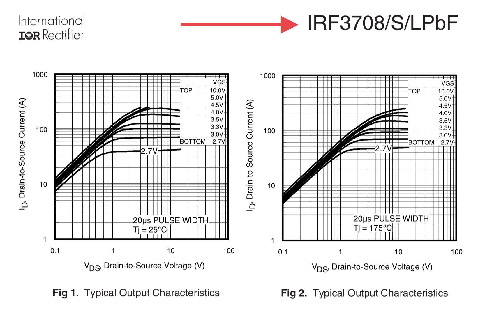
Sorry to bother you again Sir Larry , is IRL3803 Infenion mosfet better or IRF3708. Since I am going to order one of them and IRF3708 is actually not available in Amazon UK….
I will be using the low power peltier, 7.9vdc , Imax 4A .
The IRL3803 looks like it will work in your application.
However, if you can easily find IRF3708 suggest you use it.

Sir Larry , can you suggest me other transistor similar to IRF3708pbf bcz it’s not available and I’m not good at electronics ![]()

IRLB8721 looks okay.
![]()
Sir Larry
IRLB8721 or IRL3803 ? What would you recommend now ?
Either one, but IRL3803 looks a bit better.
Hello Sir Larry , I hope you’re fine … I am attaching the file , plzzzz can you explain the circuit . How it works with detail…. Especially IRL3803 mosfet . I am using PID in arduino coding. I am attaching the picture

R4 is needed to keep the MOSFET turned off when the power is first applied to the overall circuit.
The Arduino D3 output pin presents either a HIGH (5V), or LOW (0v) to resistor R3.
Current thru R3 charges the MOSFET internal capacitance, but more importantly, the 5 volts turns ON the MOSFET.
When the MOSFET turns on, the MOSFET resistance goes from very high (mega ohms) to very low (milli ohms).
The MOSFET part number was chosen so it will work with 5v to 0v changes on the MOSFET gate.
The load in the circuit is the ≈ 2 ohm Peltier cooling element.
When the MOSFET turns on (milli ohms) the bottom of the Peltier cooling element sits at zero (0) volts.
Since the top of the Peltier cooling element is at 8v and bottom is at 0v, there is 8v across the Peltier cooling element.
Ohms law says 8v ÷ 2Ω = 4 amps flowing thru the Peltier cooling element.
We use Arduino pin D3 as it is a PWM pin that we can modulate with software (PID control) and hence control the temperature from the Peltier cooling element.
Wonderful sir , thank you so much .
If anything you wanna add, plzzz do it bcz I really wanna improve my knowledge…
Thanks a lot again Sir
R4 is needed to keep the MOSFET turned off when the power is first applied to the overall circuit.
Sir why ?
And also explain a little bit more about R4 and R3…. Why R3 is 220ohm and why using it ?
You should Google PWM to see what it is and understand how it can be used (in your project) to control the Peltier cooling element temperature.
When the Arduino is first powered up, the output pin D3 is floating, not HIGH not LOW.
As a result, the MOSFET can possibly turn on by itself which can be a problem.
The 10k R4 makes the output pin D3 LOW at power up time, hence preventing the MOSFET from accidentally turning on a power on time.
R3 is 220 ohms; this is a low enough value to easily operate the MOSFET and keeps the rise time slow to keep high frequency noise problems from occurring.
R3 also keeps the Arduino output current to a safe level.
R3 is for the protection of mosfet or arduino ?
R3 protects the Arduino by keeping output current to a safe level.
AND
R3 slows the switching time of the MOSFET which reduces high frequency switching noise.
Hello Larry Sir. I need your help again. I have created the capacitive type level sensor with its additional circuit by using 741 IC . I am getting an output of 0 to 14VDC with respect to the level scale of 0 to 730mm . i want to monitor this on arduino but i think i cannot use 0 to 14VDC on arduino analogue input. so what is your suggestion ?
Search for voltage divider and use one to get the voltage down in the range you need.