Good morning! Long time reader, first time writing in! I'm working on a project that includes multiple RGB LED lighting zones with independent color control over each zone. The overview here is that eventually I will write or find an android app to run on a tablet that will communicate over the home wifi to a Raspberry Pi, which will interpret the commands into macros that will control an Arduino driving a set of TLC5940 LED drivers. It'll allow me to select colors for individual zones or trigger effects like flashing or a randomizer. I'm going in way over my head here, but that's what makes it fun!
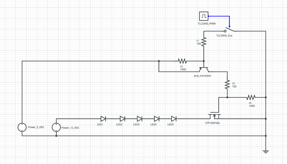
So long story short, I made a tiny little mistake reading the TLC5940 spec sheet and thought that it would SOURCE 20ma/channel, but instead it SINKS 20ma/channel! Oops! I already have the TLC5940's, several rolls of RGB LED strips, and a whole pile of STP16NF06L N-Channel mosfets. I think I have a solution to my problem, which is to use a PNP transistor to invert the voltage from the TLC5940 so it can drive the mosfets. I'm just a little hung up on the value of the transistor or if it would be better to use a P-Channel mosfet, or if there's a better solution that I just haven't come across yet. I've attached my circuit, let me walk you through it and issue way too many caveats and apologies:
-
I made this using a website called SystemVision. It's okay, it lets you simulate your circuit so I know that it roughly works.
-
There are two power supplies, a 12 VDC for the LEDs and a 5 VDC for the TLC5940 chips and Arduino.
-
The RGB LED strips are the common ones that seem to be everywhere now, they are common anode so you supply 12 VDC to a single channel and turn individual color channels on and off by shorting them to ground. It's the same product described on Adafruit here: Schematic | RGB LED Strips | Adafruit Learning System
-
I may have 10 or more segments on a single leg, each segment has three channels R, G, and B and each channel can draw 20ma per segment. So each channel has to be able to handle at least 200ma. The RGB LED strips are represented crudely by the 5 diodes across the bottom of the schematic.
-
The digital pulse and switch at the upper right are the closest I could come up with to represent the TLC5940. smh.
-
The values of the resistors shown are place holders, I figure they'll depend somewhat on the value of the pnp transistor and may vary somewhat depending on how many LEDs are on that particular leg. The ratios should be correct though, R2=R1x10 and R4=R3x10. If you want to take a stab at finding values for them you're more than welcome to and thank you.
-
This is NOT the complete circuit, just the portion of the circuit pertaining to the LED control and it's full of placeholders and ugliness. That being said, there should be enough information here to predict a good fit for that pnp_transistor right there in the middle. I've attached the spec sheet for the mosfet and
for the TLC5940the rough circuit, below is the link for the TLC5940 spec sheet which is too large to attach.
http://www.ti.com/lit/ds/symlink/tlc5940.pdf
Happy to answer any questions!
STP16NF06L.pdf (274 KB)
