I have read a lot of webpages now concerning how to move the UART0 Tx output from pin 16 to pin 11.
But it is very confusing so I want to outline what I need to accomplish by this function:
I have a sketch based on the WiFiTelnetToSerial example but modified for our needs.
The problem I have is that using UART0 for the physical line to the external device makes the ESP-07 send a bunch of extra data from boot loader on start-up, which I must get rid of.
By what I have read I could use the swap() function to make UART0 use UART1:s Tx line (on pin 11) rather than the standard TxD0 on pin 16. This pin is silent during boot-up.
But I am getting confused by reading the information I have found on how this works. Will it just swap the Tx line while keeping the original Rx line? Or is this also swapped away somewhere?
For example if I wire the serial interface to pins 11 (TxD1) and 15 (RxD0), how can I then program the device firmware?
For programming flash I believe that the TxD0 on pin 16 must be used, but when using the swap I have to wire the board so the external serial line would go to TxD1 on pin 11 instead...
So how can this be solved?
I have asked about this in other threads as part of other discussions but now I create a thread just for this single question to make it clearer...
I still don't understand how to fix it.
Additional info:
I have checked what comes out on Serial and Serial1 at boot and the first sequence is exactly the same on both ports!
So it seems like it would not even help by using TxD1 as the output channel. It too is sending garbage during boot.
Remains a hardware solution with a gate that blocks the data to reach the TTL/RS232 level converter for some limited time during boot. Don't know for how long though...
So I have to create a zero value pulse starting at power on and if the reset is used with a time lasting for some hundred milliseconds after which it goes to 1. And this must control an AND gate feeding TxD0 to the level converter.
Not fun...
Serial swap has nothing to do with Serial1. The ESP8266 has two hardware UARTs: UART0 on pins 1 and 3 (TX0 and RX0 resp.), and UART1 on pins 2 and 8 (TX1 and RX1 resp.).
UART0 also has hardware flow control on pins 15 and 13 (RTS0 and CTS0 resp.). These two pins can also be used as alternative TX0 and RX0 pins. That's what Serial.swap() does.
I have decided to put a 1-channel MUX 74LVC1G157 in series with the TxD0 signal (from pin 16) and connect the gate signal from GPIO5 (pin 5) with a pull-down resistor. Since the ESP-07S at reset puts all GPIO pins as inputs it wil make the gate signal 0 and this will block the extra data from reaching the TTL/RS232 level shifter.
In my sketch code I will set GPOI5 as as output and set it to high, which will make the serial data transfer to the output pins.
For initial programming I will put a jumper in place to force the gate signal high at all times so the flashing can work as needed.
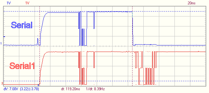
I made a check on what comes out both serial ports during the boot and I found that after 50 ms both ports output the extra data. Then 119 ms after power-on both outputs go to zero and on Serial1 (my debug channel) my programmed data appears with a 4 ms delay.
So I figure that if I raise PGIO5 first thing inside setup(), then what is output on Serial will be sent correctly.
I attach the scope output from my test. I cannot see how I can make it part of the actual post (so the image shows up)....
Since from the replies I have received it does not solve the problem...
Swap will not be effected until my code starts running, which is some 119 ms after power-on.
During that time the ESP-07S spews out serial data which I have to block.
All pages I have read state that Expressif has set the chip up so it will always send these data on both the Serial and Serial1 outputs and I have verified this with my oscilloscope (did you look at the image I posted?).
This leaves only a hardware solution to get rid of that disturbing output data....
OP:
Back when you started this topic, you stated in this post: Is there a way to stop serial output on boot for an ESP8266 module? - #8 by BosseB - Programming Questions - Arduino Forum that your data transmission is formatted into packets with checksum verification. Have you since then confirmed that this initial garbage transmission actually breaks your packet protocol and causes undesirable behavior in the remotes? If not, it seems like you're putting a lot of effort into solving a problem you may not have.
BosseB:
Since from the replies I have received it does not solve the problem...
Swap will not be effected until my code starts running, which is some 119 ms after power-on.
During that time the ESP-07S spews out serial data which I have to block.
All pages I have read state that Expressif has set the chip up so it will always send these data on both the Serial and Serial1 outputs and I have verified this with my oscilloscope (did you look at the image I posted?).
This leaves only a hardware solution to get rid of that disturbing output data....
You just have to connect your device to GPIO15 and GPIO13. It doesn't send anything at boot, and it it only starts sending out data after you call Serial.begin() and Serial.swap().
OK, I was under the impression that swap() would swap the Tx lines for Serial and Serial1, i.e. TxD0 would be on pin 11 (GPIO2) and TxD1 on pin 16. (Swap to me means exchanging two items)
If what it does is to move Serial TxD to GPIO13 (pin 7) then I have not checked that at all.
But if it works I still have the problem of how to initially program the flash on the board, if I move TxD from pin 16 to pin 7 in the board layout the serial connection will not work for flashing the module...
I guess I would have to provide the board with some jumpers for that purpose...
gfvalvo:
OP:
Back when you started this topic, you stated in this post: Is there a way to stop serial output on boot for an ESP8266 module? - #8 by BosseB - Programming Questions - Arduino Forum that your data transmission is formatted into packets with checksum verification. Have you since then confirmed that this initial garbage transmission actually breaks your packet protocol and causes undesirable behavior in the remotes? If not, it seems like you're putting a lot of effort into solving a problem you may not have.
Yes, that is true but I am not 100% sure that there will be no such interference so I would rather that the line stays silent..
Just to make sure I got this right in the end:
If I do this in my code, what will happen:
    #define SERIALPIN 13  //Shift Serial Tx data to pin #7 = GPIO13, will be in header file
    Serial.begin(ESPConf.baud);  //Start Serial with configured baudrate
    Serial.swap(SERIALPIN);    //Move the serial tx pin to GPIO13
Does this mean that after it has executed then the Serial Rx is still on GPIO3 (pin 15) while the Serial Tx pin is now GPIO13 on pin 7 rather than GPIO1 on pin 16?
Or do I have to say which pin should be swapped (rx or tx)?
If this is OK then I can use my MUX with a jumper to select which pin (16 or 7) should be routed to the serial interface Tx pin. Like so:
Jumper in for flash programming (once only because I have included the WebUpdater function in my code).
Jumper away and pin 7 feeds data to the external serial interface and is silent during boot.
BosseB:
Just to make sure I got this right in the end:
If I do this in my code, what will happen:
#define SERIALPIN 13 //Shift Serial Tx data to pin #7 = GPIO13, will be in header file
Serial.begin(ESPConf.baud); //Start Serial with configured baudrate
Serial.swap(SERIALPIN); //Move the serial tx pin to GPIO13
Does this mean that [u]after it has executed[/u] then the Serial Rx is [u]still[/u] on GPIO3 (pin 15) while the Serial Tx pin is now GPIO13 on pin 7 rather than GPIO1 on pin 16?
Or do I have to say [u]which[/u] pin should be swapped (rx or tx)?
Notice the parameter tx_pin! No sign of rx_pin so either it is selected by the tx_pin setting or it is not changed...
This indicated to me that one can use any pin available, but unfortunately it is not really documented.
Also there is no mention of the rx pin, so I assumed it stays put during a swap.
If not I would really like to see a description that also mentions all available overloaded swap() methods and the arguments used.
The FM seems to only address swap() without arguments, which switches both Rx and Tx at the same time to fixed targets:
Tx/Rx = GPIO1/GPIO3 vs GPIO15/GPIO13
So if I adopt the simple swap() I need to hook up my RS232 system to pins GPIO15/GPIO13 and possibly provide another connection on the board to reach the GPIO1/GPIO3 standard mapping which will be used when starting in flash mode when we first initialize the boards.
Why need to program the module?
Well when you get delivery of a bunch of ESP-07S they come with the Ai-Thinker AT-firmware, which needs to be replaced.
In this situation there is afaik no other programming method than via the serial port from Arduino, Sloeber or a standalone programmer. So this is what we need to do. We at this time also need to erase the complete flash memory of the ESP module, but that is part of the IDE command.
But this can not happen until the module is soldered to our board and here I will have to provide a way for the programmer to reach the standard Serial port on pins 15/16 of the module.
But the pin 16 TxD0 spews out the extra data on boot I want to avoid for example by using swap().
So for the final situation the serial connector on our wifi board must go to the swapped pins of the ESP module rather than 15/16...
But for programming it needs to go to 15/16...
Since our firmware contains the WebUpdater function this is a one-off operation, all following firmware updates will be done via WiFi.
And we "know" that down the line we will need to provide a way to update the WiFi module firmware, which is much simplified using the WebUpdater library.
We are making something like 50-100 systems a year each containing 1-2 such boards.
And we need to replace an older solution with the ESP one.
Everything works except for this issue.
If the programming has to be done only once, is it fealible to use a small on-board header to connect to GPIO 1 & 3 for programming, while leaving the RS232 connected to GPIO 15 & 13? Or does the programming have to happen over the same RS232 port?
I never knew that you could alter the pins of the UART, I thought that Serial.swap() was the only option.
I would try that function first, since it is guaranteed to work. There doesn't seem to be much information on uart_set_pins.
Problem resolved!
Last night I decided to do as follows (which is pretty much what PieterP suggested today:
Use the Serial.swap function without arguments. Should put Rx/Tx on pins 7/10
Wire pins 7/10 as the serial connection to the outside world
Add a 2-pin header next to pins 15/16 to connect an USB/SerialTTL cable for initial programming
Today I prepared a breadboard prototype to test this. The wired up prototype using our old board as base had ESP-07 pins 9/10 hard soldered on the underside of the module so it is not possible to modify...
And with the breadboard I have found that I have no on boot data on the serial output from the ESP-07S but the serial server function is now running fine on pins 7/10.
The only extra data I can see in the terminal is a single null char when the module boots, and this is probably due to the level shift on the pin when the Serial.begin(baud) is executed, when the pin changes state...
So I am good now, that NULL will not cause trouble.
EDIT:
Except I did not notice the linked topic about being unable to send NULL bytes with a swapped serial...
I really hope this is not what the chip does, because our data are binary and will contain many NULL bytes...
I loathe the people that reply with "RTFM" because it implies that the person raising the question hasn't. Sometimes, people can't find the appropriate manual of which you speak. Once they are pointed in the right direction, they will probably be "enlightened" just like you are!
johncblacker:
I loathe the people that reply with "RTFM" because it implies that the person raising the question hasn't. Sometimes, people can't find the appropriate manual of which you speak. Once they are pointed in the right direction, they will probably be "enlightened" just like you are!
Could you please specify clearer what/who you are complaining about in this thread I started May 14, 2018? I was perfectly satisfied with the responses to my questions and the advice/links provided. After a while the discussion cleared a misconception in my mind concerning what exactly Serial.swap() does and then I could wire up my board in a working way.
Production boards now manufactured and work well.
I agree with the guy criticizing the RTFM. I have been there only to do the head-slap after reading forum comments.
I am now trying to test a bluetooth connection with a LoLin nodemcu V3, and trying to figure out which pins to connect the ZS-040 device to. I think that when you refer to 'pin 3', you mean 'GPIO3', which is stamped as D9 on the nodemcu board. (See attached)
Since you have resolved the issue, could you post the code segments ('before setup', 'during setup', and loop sections that define the operations?
lastly, you describe using the ESPsoftSerial library. My nodemcu rejected the use of Arduino's SoftSerial, and I was successful downloading the test program using Serial() and Serial1() format, but I have not yet had a successful dialog with the bluetooth. So, I am confused too!
update:
Updated Arduino 1.8.3 to Arduino 1.8.9
updated Board Manager ESP8266 to 2.5.0
assigned BlueTooth -- Rx,Tx to SoftwareSerial D7,D8 on the Nodemcu V3
GeeWhiz, it working fine!
jack23233:
I agree with the guy criticizing the RTFM. I have been there only to do the head-slap after reading forum comments.
I still think that the word "loathe" is inappropriate in a user community...
Since you have resolved the issue, could you post the code segments ('before setup', 'during setup', and loop sections that define the operations?
I have this in StartSerialServer(), which is called from within setup(). On the board the instrument serial connections are tied to pins 7 and 19 of the ESP-07S (GPIO13 and GPIO15). So not until setup() has reached the proper state is the swap done which connects the Serial UART to the physical pins to the instrument.
Whatever junk the ESP sends on its Serial unit during boot is not connected to anything at all.
Serial1.println("Swapping pins for Serial, use 7/10 for Rx/Tx!");
Serial.swap(); //Put the serial pins on 7 (Rx = GPIO13) and 10 (Tx = GPIO15) to avoid boot data to reach instrument
Nothing more was needed to silence the ESP device output.
Except I had to wire out the standard pins to a pin header so the Serial UART could be used during initial programming of the boards using a serial programmer. So the production people connect the programmer's serial lines to the pin header and hold the flash button down when they reset the board. Then it is ready to be flashed for the first (and last) time. After this we use a webupdater service running on the ESP itself to update the flash.