TPIC6B595 shift register debug question

Dear Builders,
I'm working on a project with many (literally over 120) TPIC6B595 shift registers, each driving 12 V solenoids. The project is in the prototyping phase, and now I've experienced a strange behaviour. Please, help me to find a solution to this problem.
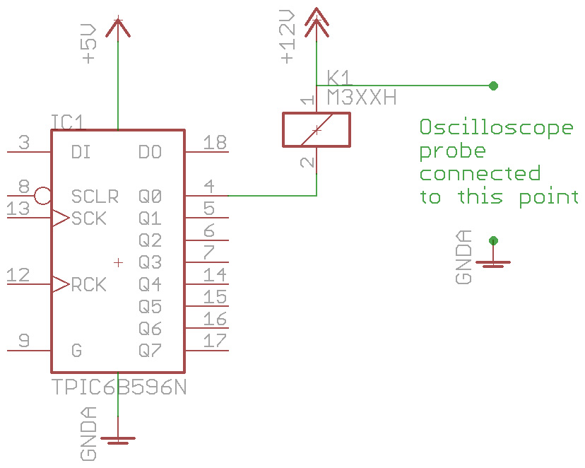
The usual current of the solenoid is 125 mA, which is close to the boundary for the shift register. The IC is connected as usual, the solenoid is connected directly to the chip, as well as to a +12 V source. Both grounds common (5 V logic and 12 V drive). At start-up, everything goes fine, until the first activation of the solenoid. It closes perfectly with a current draw of about 125 mA. This state remans for two cycles (500 ms each, one division on the picture below), then should go of. But it doesn't. It remains closed and draws 35-40 mA.
The schematics shows the measuring setup.
External link to the schematics picture.
This one representing the actual voltage change during the procedure:
External link to the oscilloscope screen capture.
At (1) 12 V source turned on (until then, the regular 5V source drives the logic and other parts of the system).
At (2) the first time when the solenoid closes, it remains closed for 500 ms (one division), until
(3), where a short (10 ms) burst puts all the outputs in passive mode (Output enable high), and back to normal (Output enable low).
Finally, at (4) the output goes off (no drain), but the system remains in closed circuit with about 35 mA of constant current until the next activation phase.
How can I fix this probllem?

Your sincerely,
Tamás

Why are you not using a kickback diode?
Are you using decoupling on Vcc.

.

  1. Tie SCLR to +5
  2. Tie G to Gnd.
  3. Add 0.1uF cap from +5 to Gnd, close to the chip as you can.
  4. Add diode across the coil, cathode to 12V, anode to the shift register side
    1N5817 Diode Schottky 1A 20V

May be the diode is optional. From the datasheet:

The device contains a built-in
voltage clamp on the outputs for inductive
transient protection.

The "G" pin as marked on the OP's schematic is actually "NOT G"

A 50 volt clamp. :wink:
Been there done that.

A LOW on G will enable the output as Crossroads implies.
.

CrossRoads:

  1. Tie SCLR to +5
  2. Tie G to Gnd.
  3. Add 0.1uF cap from +5 to Gnd, close to the chip as you can.
  4. Add diode across the coil, cathode to 12V, anode to the shift register side
    http://www.taydaelectronics.com/1n5817-diode-schottky-1a-20v.html

These steps had been done as first steps. Schematics is simplified. I've used a 1N4007 btw.

LarryD:
Why are you not using a kickback diode?
Are you using decoupling on Vcc.

See above. 100 nF decoupling on vcc.

Please show us a good image of your wiring.

.

LarryD:
A 50 volt clamp. :wink:
Been there done that.
A LOW on G will enable the output as Crossroads implies.

G is on low.

Please explain this "50 volt clamp" statement! :slight_smile:

Thanks!

LarryD:
Please show us a good image of your wiring.

This is still a prototype. By the way, I did my best.

There is a ~50 volt zener on the output of each FET that clamps positive voltages to 50 volts.
This may be good enough for kickback protection, however, having 50 volt spikes on each output is far from good design, if not ignoring the fact that a 50V spike is not a good thing to have in digital circuits.

Stay with your 1N4007 across the coils.

Lots of antennas in those long wires.


.

Funny, that solenoid looks like it would draw more than 125 ma at 12V.

What is the resistance of the coil?

Edit
If your scope is looking at the solenoid plus supply to GND, you have a serious problem with the solenoid power supply.
.

Why do you measure the +12volt (pin1 of the solenoid) point.
You should be measuring Q0 (pin2 of the solenoid).
That should go zero when the solenoid is active, and return to +12volt after the 50volt kickback spike.

If that +12volt supply doesn't stay 12volt all the time, there is someting wrong with the 12volt supply.

Did you connect ground of the TPIC both to 12volt negative, and to Arduino ground.

Having to use a diode across the relay is BS.
These chips have an active clamp.
I currently have 24 relays on a board working fine without diodes.
Note that solenoids/relays will turn off faster without diodes.

And yes, you should post the resistance of the coil.
The datasheet lists a one-output current limit, and an all-outputs current limit.
Leo..

"Having to use a diode across the relay is BS."

Across the solenoid.
The OP will be driving 120 of these solenoids.

Anyway, as i said "been there done that".

.

Just saw that OP is also using indicator LEDs.
Then it might be wise to use diodes across the coils.
The LEDs might not like a 50volt reverse spike.
Leo..

LarryD:
There is a ~50 volt zener on the output of each FET that clamps positive voltages to 50 volts.
This may be good enough for kickback protection, however, having 50 volt spikes on each output is far from good design, if not ignoring the fact that a 50V spike is not a good thing to have in digital circuits.

Stay with your 1N4007 across the coils.

Lots of antennas in those long wires.


.

Hi Larry,

Thanks for taking time to deeper inspection.

Yes, that's true. I'm working on it (to eliminate all possible spikes).
Long wires will reduced in the final product (serial production PCBs will used).

Here are the answers to your questions:

  1. Yes. The oscilloscope probe is connected to the positive side of the solenoid and to common ground. The result is the same with some math difference on the opposite side.
  2. Power supply: a PC power supply, so I suppos, it's regulated, meanwhile not perfect.
  3. The long red wire is a power line between two supply line of the breadboards. Due to a stupid decision I've made design, I used the negative side on that rail as positive side (all LEDs are connected to this).
  4. The decoupling capacitor is connected just to next pinhole to the vcc and gnd pins, so yes, it's close.
  5. Nano is powered from the same source as the solenoid (PC power supply). Of course, from the 5V line. Grounds are common on both ends (PS and breadboard).

If you have any suggestion for a better setup for inspecting the issue, just let me know, and I'll work on it.

Thanks again,

Tamás

LarryD:
Funny, that solenoid looks like it would draw more than 125 ma at 12V.

What is the resistance of the coil?

Edit
If your scope is looking at the solenoid plus supply to GND, you have a serious problem with the solenoid power supply.

The solenoid draws 125 mA when connected to 12 V. At this point, 10,55 V measured on the pins.

I do not have any specs for the solenoid, and as far as I know, it's a bit more complicated to calculate the resistance than making a simple measurement with a multimeter. Above data may help a bit.

Yes, it's possible. By the way, I'm going to fix it.

If this scope image is looking from +12v to GND, there is simply something wrong with the power supply.
It should remain at 12 volts wether the solonoid is picked or not!

Just measure the coil resistance with an ohm meter.

.

Dear Leo,

Thanks for the answer.

Wawa:
Why do you measure the +12volt (pin1 of the solenoid) point.
You should be measuring Q0 (pin2 of the solenoid).
That should go zero when the solenoid is active, and return to +12volt after the 50volt kickback spike.

It was just one way to make measurements. Today I've made more with both pins measured with an individual probe. (Yellow is on the positive side, light blue is on the negative side, dark blue is a Math with lightblue (minus) yellow).

Yes, you're right. But it's not true unfortunately. It doesn't go back to the normal level.
In short (see the picture, sorry for the quality, screenshot didn't work):
negative side: normal state: +12.6 V, activated state: around 1.1 V, deactivated state: 8.2 V.
positive side: normal state: +12,6 V, activated state: around 11.5 V, deactivated state: 3.5 V.

Wawa:
If that +12volt supply doesn't stay 12volt all the time, there is someting wrong with the 12volt supply.

It seems a real issue here. I have couple of other sources, will make some tests tomorrow.

Wawa:
Did you connect ground of the TPIC both to 12volt negative, and to Arduino ground.

Of course not. It could be a misunderstanding that one negative supply line on the breadboard were used as a positive supply line. It was way easier to do so than to relocate 8 resistors.

Wawa:
Having to use a diode across the relay is BS.
These chips have an active clamp.
I currently have 24 relays on a board working fine without diodes.
Note that solenoids/relays will turn off faster without diodes.

And yes, you should post the resistance of the coil.
The datasheet lists a one-output current limit, and an all-outputs current limit.
Leo..

I don't have any specs unfortunately. It's only a one piece sample from China. Will have more in the close future with better documentation (meanwhile anything is better than nothing).

Thanks for your assistance and ideas,

Tamás

LarryD:
Just measure the coil resistance with an ohm meter.

86.8 Ohm.