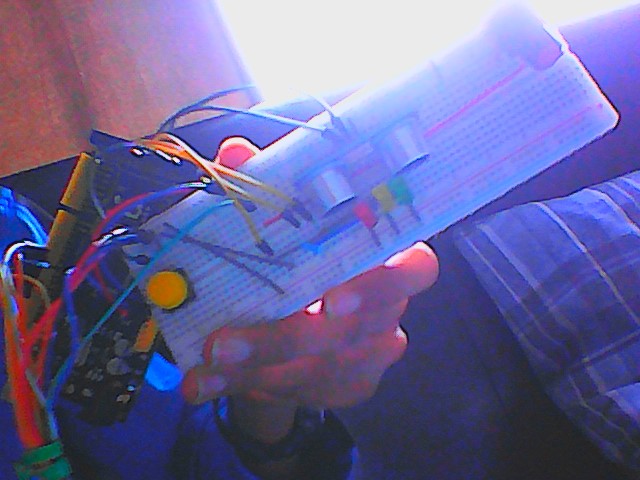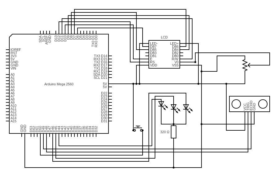
that is my circuit, but the code keeps on getting stuck when it turns on the green light. I want it to use the button to change priorities, 1 mode to turn green when the ultrasonic sensor reads something close enough, and the other time based.
here is my code.
#include <SR04.h>
#include <LiquidCrystal.h>

#define TRIG_PIN 48
#define ECHO_PIN 49

const byte BUTTON = 50;
const byte redLED = 44;
const byte yellowLED = 45;
const byte greenLED = 46;

bool Bool_mode = false;
bool Bool_greenProcessStart = false;
bool Bool_yellowProcessStart = false;
bool trafficStart = true;

unsigned int photoValue;
long ultrasonicInput;
int ultrasonicInterval = 500;
unsigned long ultrasonicPastTime = 0;
int trafficLightProccesRestartInterval = 60000;
unsigned long trafficLightProccesRestartPastTime = 0;
unsigned long greenPastTime = 0;
int greenInterval = 15000;
unsigned long yellowPastTime = 0;
int yellowInterval = 40000;

LiquidCrystal lcd(12, 11, 10, 9, 8, 7, 6);
SR04 sr04 = SR04(ECHO_PIN,TRIG_PIN);

void setup() {
  delay(1000);
  pinMode(BUTTON, INPUT);
  lcd.home();
  lcd.print("start");
  Serial.begin(9600);
}

void loop() {
  unsigned long currentTime = millis();
  if (digitalRead(BUTTON) == HIGH) {
    delay(100);
    if (Bool_mode == true) {
      Bool_mode = false;
    } else {
      Bool_mode = true;
    }
  }
  if (currentTime-ultrasonicPastTime >= ultrasonicInterval) {
    ultrasonicPastTime = currentTime;
    ultrasonicInput = sr04.Distance();
    Serial.println(ultrasonicInput);
  }
  if (Bool_mode == false) {
    if (currentTime-trafficLightProccesRestartPastTime >= trafficLightProccesRestartInterval || trafficStart == true) {
      trafficStart = false;
      trafficLightProccesRestartPastTime = currentTime;
      Serial.println("reset");
      digitalWrite(redLED, LOW);
      digitalWrite(yellowLED, LOW);
      digitalWrite(greenLED, LOW);
      digitalWrite(redLED, HIGH);
      Bool_greenProcessStart = true;
      Serial.println("Bool_greenProcessStart = " + Bool_greenProcessStart);
      greenPastTime = currentTime;
      lcd.clear();
      lcd.home();
      lcd.print("reset");
  }
    if (Bool_greenProcessStart == true && currentTime -greenPastTime >= greenInterval) {
      Serial.print("green");
      digitalWrite(redLED, LOW);
      digitalWrite(greenLED, HIGH);
      yellowPastTime = currentTime;
      Bool_greenProcessStart = false;
      Serial.println("Bool_greenProcessStart = " + Bool_greenProcessStart);
      Bool_yellowProcessStart = true;
      Serial.println("Bool_yellowProcessStart = " + Bool_yellowProcessStart);
      yellowPastTime = currentTime;
      lcd.clear();
      lcd.home();
      lcd.print("greenOn");
  }
    if (Bool_yellowProcessStart == true && currentTime - yellowPastTime >= yellowInterval) {
      Serial.println("yellow");
      digitalWrite(greenLED, LOW);
      digitalWrite(yellowLED, HIGH);
      Bool_yellowProcessStart = false;
      Serial.println("Bool_yellowProcessStart = " + Bool_yellowProcessStart);
      lcd.clear();
      lcd.home();
      lcd.print("yellowOn");
    }
  }


}
how do I fix this?