In general, transistor is a current activated device, so the collector emitter voltage drop is dependent on both current being switched / passed and the controlling current.
We do not know how much controlling current is supplied by the processor.
From the data sheet the collector emitter drop is from 2 to 4 V , but 4V is with 5 A(!) current being passed.
Much less drop with what you will be switching, again from data sheets.
In theory your setup is only switching max 2 LED's in parallel ( 2 x 350 ma max) per TIP120 so it should work OK from 5 V supply, assuming max 3 V drop per LED.
But that is definitely on borderline, 12V would be safer with the additional resistors.
You could just add one common drop resistor into the ground connection, properly calculated for max count of LED switched at one time.
But the cool way to do this would be to actually use the PWM to control the effective driver current to the each TIP120.
Good luck
See two images below:
Are you saying that just increasing the voltage to 12V would not work? Or, are those diagrams explaining how the top TIP120s could be used to regulate the the LED current like Vaclav explained?
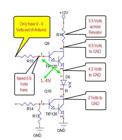
Where are you getting the 5.5V drop value over the resistor? Edit: Nevermind, I see you wrote above that 12V - 2V(TIP120) - 2.5V(LED) - 2V(TIP120) = 5.5V (across the resistor).
Also, I measured the actual voltage drop across one of the bottom TIP120s (the ones that control on/off) and it is only 0.6V. Is this because the overall voltage (5V) is inadequate, so 0.6V is all that's left by the time it gets to the second TIP120?
I measured the actual voltage drop across one of the bottom TIP120s (the ones that control on/off) and it is only 0.6V
This does depend on other voltages, if the transistor is saturated and the amount of current that is flowing through the transistor.
Worst case (assumption is) 2-6 volts. If you are measuring .6Vce at a current of 200mA then you have to recalculate your series resistor using this voltage.
It is always best to use your voltmeter to confirm any assumptions.
You have two problems the first one I mentioned earlier, when you were using a 5 volt supply and therefore not enough to drive the LEDs.
The second one, where the Arduino output isn't going to be sufficient to turn on the top transistor as it's Base needs 5.9 volts. The Arduino can only output 5 volts maximum (this exists no matter what the power supply voltage is).
I still don't understand why this now wouldn't work without an additional transistor driving the upper TIP120 if the voltage was increased to 12V.
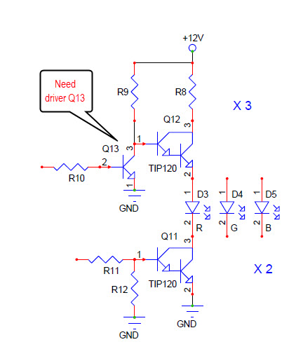
You will need the driver transistor on the top TIP120 (as in 2nd image).
If I were you I would hook up a test circuit as in the 2nd image for one LED to confirm it will work as I have said, then proceed with your project.
If it was me, I would either use MOS FETs or, in your design, change the top transistor to a TIP127(PNP) with TIP120(NPN) in the bottom (I have not shown a image of this option as of yet).
The real problem here is you have to confirm things prior to construction, a trait we all have to attain.
I would use a software PWM library with 2 ULN2003..........
unless you really need the pins to do other stuff.
Could the driver transistor just be something small like a 2N2222? I'm assuming R9 and R10 in your drawings would still be something like a 1K resistor, but with the driver transistor, it would supply 12V through the 1K resistor to the TIP120 whenever the driver transistor is off, correct?
How would changing to a TIP127 for the top transistor change things? Obviously I would have to invert my PWM signal (0% would be full on, 100% would be full off.) But, wouldn't I need the same 5.9 volts supplied to the base in order to turn off the transistor? Or, does the TIP127 not have the same voltage drop when it's non-saturated and allowing current flow that a TIP120 has when it's saturated, allowing me to keep my original 5V design?
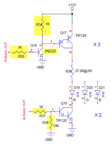
Sorry, the PNP at the top should be a TIP127 not a TIP129.
Ok, so you're just inverting the signal again using the TIP127 so I don't have to invert it in the software.
Is there a reason you moved the current limiting resistor to after the TIP127?
Last, what is the purpose of R38, the 10K resistor?
Thanks.
I moved the LED resistor because in switching applications you want a common emitter configuration (no resistor between the emitter and the power supply +12V as in the TIP127, and the GND(0V) in the TIP120).
The purpose of the 10K resistor is to make sure the TIP120 is turned off during power up, when the Arduino is in a Hi Z state (all pins in the IINPUT mode).
EDIT:
A LOW output from the Arduino to the 2N2222 turns it OFF. The 12V at it's collector turns the TIP127 OFF.
A LOW output from the Arduino to the TIP120 will turn off the TIP120.
So if I stay with the TIP120, I should keep the current limiter before the TIP120?
Back to using only TIP120s?
Use a driver when the LED power supply voltage is greater than 5 volts.
Hook up a test circuit to confirm it will do what you think it will do.
I'm just trying to figure out the simplest direction to go from here without tearing up what's already done too much. Changing the power supply to 12V and just sticking a driver on the upper TIP120s is the simplest thing to do. I know, I should have investigated it further before I assembled it, but I was completely unaware of the complexities of using the TIP120s in this way. I thought they were nothing more than an on/off switch, and did not realize they dropped voltage.
Thanks for clarifying this. I wish I was more knowledgeable with regard to electronics. I know the basics, and what I've taught myself, but beyond that, it's sketchy. Are you an electrical engineer?
I'm just trying to figure out the simplest direction to go from here without tearing up what's already done too much. Changing the power supply to 12V and just sticking a driver on the upper TIP120s is the simplest thing to do. I know, I should have investigated it further before I assembled it , after a couple of projects we all learn always best to try part of the circuit or write part of the code before committing too much but I was completely unaware of the complexities of using the TIP120s in this way. I thought they were nothing more than an on/off switch, nothing is ideal and did not realize they dropped voltage.
Thanks for clarifying this. I wish I was more knowledgeable with regard to electronics lots of info on the WEB . I know the basics, and what I've taught myself, but beyond that, it's sketchy. Are you an electrical engineer long since retired?
Thinking some more, couldn't I swap out the 2N2222 for a 2N2907 to keep the operation of the PWM signals similar to having the Arduino directly controlling the TIP120?
As it stands, with the 2N2222, whenever I want the on time of the TIP120 to be higher, I would actually duty cycle the output to the 2N2222 lower. But if I substituted a 2N2907, then providing higher on time to it would also result in the TIP120 having a higher on time. Yes?
Also, I measured the actual voltage drop across one of the bottom TIP120s (the ones that control on/off) and it is only 0.6V. Is this because the overall voltage (5V) is inadequate, so 0.6V is all that's left by the time it gets to the second TIP120?
An expected drop with about max . 7 A ( STEADY, not PWM!) , passing thru , per datasheet. So you have 5v - 1.2v left for the LED.
As I said before OK, but borderline with 5V power supply for LED's.
Actually you should measure the current to get a better picture or answer why the LED are not as bright as you excpected, as you stated in the OP.
Since the Arduino only goes to +5V the 2N2907 will never turn OFF.
You could place an inverter between the Arduino and the 2N2222 driver if needed.
Thanks everyone. Everything is working much better running the system at 12V with 2n2222s driving the upper TIP120s. Now I just need to work the bugs out of the code. ![]()
Good for you for sticking with it.
Get into the habit of bread boarding your circuits before you commit to a design.
Have on hand some N and P channel FETs ( logic) some TIP120s TIP127s 2N5088s different multiplexers and other commonly used components.
Use your voltmeter to confirm operating levels.
Also actual voltages compared to design voltages.