I'm working on a very basic 4x4x4 LED cube. They're single color LEDs (blue, in my case) with a max forward voltage of 3.2v. I understand (conceptually) everything about how the cube functions with the exception of one thing: the transistors I need to control each horizontal "layer" of the cube.
Some basic info:
Using a standalone ATMEGA328P
16 vertical cathode columns driven by two 74HC595 shift registers
4 horizontal anode layers
Why?:
To learn & understand multiplexing with shift registers better
To learn about PCB creation for small projects
To have a cool thing to play with
I have the following schematic (please be gentle, I'm still learning how to make schematics):
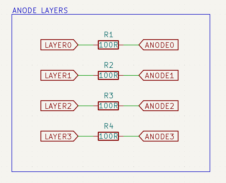
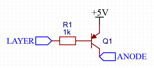
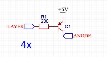
My confusion is how to control the 4 anode layers. I have seen many people using NPN BJT transistors, but they tend to have common cathode layers instead of anode - which leads me to believe that I need 4 PNP transistors? Is that logic correct?
My understanding is that at any given time, only one layer will ever be "lit" at once, meaning a maximum of 16 LEDs will be on. If each LED has a forward current of 20mA, then at most I need a transistor that can handle 16 * 20mA = 320mA at once. Assuming I was right about needing a PNP transistor, would a 2N2907 PNP transistor be fine? It can handle 600mA.
If that is sufficient, how do I go about connecting it in my schematic? I'm assuming it would be placed somewhere in here:
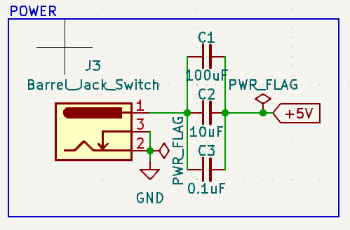
I'm learning KiCad and I think PWR_FLAG is something you add in to let the rule checker know that that is a power source. I'm following a video tutorial and this was the solution mentioned in it.
I'll be honest, when it comes to the power, I'm also a bit confused. I want to power this thing with an external 5V wall wart, and I believe that's the correct connector for it. To fix the short, would I need to connect the capacitors to the GND as well?
Thank you very much for this - this is very helpful for me!
I'm playing with the 74HC595's because I also want to play with the brightness of each LED. Also, I am (very slowly) working up to making an RGB version of this, and then eventually an 8x8x8 version. I think the 74hc595's are fun, and I enjoy the look of the component-rich designs. I know it's probably not the most efficient, but it's all in the name of learning.
For the current limiting resistors -- I would need one per column? (so 16 total) For some reason I thought one per layer would be enough. It's so hard to gauge the quality of Instructable pages.
If you use only one resistor per layer, you will need to multiplex the cube column-by-column. If you try to multiplex it layer-by-layer, there will be a problem because when only one led is lit on the layer, it will be much brighter than when all 16 are lit. This is because however many LEDs on the layer are lit, they will all have to share the current passing through that one resistor.
If you multiplex column-by-column, each led can be on for a maximum of 1/16th or 6.25% of the time. If the current flowing through the led when it is on is 20mA, then the average current will be 20 x 1/16 = 1.25mA.
If you multiplex layer-by-layer, each led can be on for a maximum of 1/4 or 25% of the time. The average current would be 20 x 1/4 = 5mA.
The average current flowing though the LEDs determines how bright they appear.
The suggested TPIC6B595 chip will not prevent that, or make it easier.
The suggested TPIC chip will not change the number of components required for your cube.
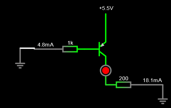
Here is a question for you: what is the maximum current that a 74hc595 chip can source or sink, across all its 8 output pins simultaneously? How will this limit affect your design? Answering this question may help you understand why the TPIC chip was suggested as an alternative.
True, but this will reduce brightness on all outputs/LEDs by the same amount. @n0ahhh said that they want to
This is possible with 74hc595 or tpic6b595, but the brightness control will need to be done in software because the hardware does not support it. This means using a significantly higher refresh rate, allowing the arduino to independantly control the % of time that each led is lit.
Using this or similar designs will become significantly more difficult with RGB and larger cubes. You are right to begin with a smaller simpler cube as a learning experience.
If I wanted to build an RGB cube of any size, I would try to make a design using "smart" LEDs like ws2812 or apa106. These LEDs have shift registers built into each led, simplifying the design and increasing the brightness by eliminating the need to multiplex, and allowing individual control of the colour and brightness of each led. They are available in the 5mm or 8mm round design which look good in cubes.