Transistor heating up

Hello :slight_smile:

I have been learning by experimentation and reading documentation, but I am hitting a wall where I cannot understand why is my transistor heating up so fast to very high temperatures melting the plastic of the breadless board pins.

I am trying to control the motor speed by a sonar sensor the closer the obstacle is the slower the motor will spin.

I have attached the schematic the only difference is the 9V battery is an AC adapter outputting 12v and 2A
other parts:.

BDBD681G NPN transistor
HC-SR04 Ultra sonc Sonar range finder.

Please let me know if you can spot what I am doing wrong. :frowning:
Thank you so much for your time and attention :slight_smile:

In the photo, it's not possible to see which way round you have the BD681.
If it's the same as in the Fritzing diagram, you have it wired incorrectly.
When looking at the transistor from the front, the pins (left to right) are:-
E C B

Which means that you have the base connected to ground, and you're driving the emitter. ie It's backwards.
Again, that's assuming the front of the real transistor is where the flat side is in the Fritzing diagram.

And by the way, a Fritzing diagram is not a schematic diagram. (Personally, I hate Fritzing diagrams.)
A real schematic diagram is far more useful, and contains much more information if correctly labelled.

Can't find "BDBD681G"
Do you mean a BD681 (darlington).

That transistor might have a saturation voltage of ~1volt with a 220ohm base resistor (can't see the real value).
Heat generated depends on motor current.
0.5A (0.5watt) might just be ok without heatsink.
Anything more and the transistor will get very hot.

The diode goes across the motor (cathode to +12volt), not across the transistor.
Leo..

Thank you for your swift and informative replies :slight_smile:

@Wawa I don't know how to read data sheets yet, but found a link to the transistor

I though the Adc documented at 4 will be sufficient to handle 2A coming from the AC adapter.
Also the Vdc documented at 100 I thought that would cover the 12V supplied from the AC adapter.
Please correct me if I am reading those incorrectly as I really don't know the specs or units for them at all :slight_smile:

@OldSteve I have attached a close up picture of the setup as the Fritzing doesn't reflect truly what I am doing ,I will try to use the schematic view next time.

@OldSteve I have attached a close up picture of the setup as the Fritzing doesn't reflect truly what I am doing ,I will try to use the schematic view next time.

That's why I don't like Fritzing. :slight_smile:

Well the transistor is connected correctly, but as mentioned by Wawa, the diode should be across the motor. Effectively, the transistor collector to motor +V.

Sounds like you need a heatsink, to me.
The transistor can handle up to 4A continuous, but "TC=25°C".
ie You have to keep it cool enough.

Sorry for being such a noob, would you kindly explain what do you mean by the diode should be across the motor. Effectively, the transistor collector to motor +V.

Should I rotate the diode [vertically rather than horizontally] and put it between the transistor collector and the motor +V? I just thought to double check before doing any damage to any of the parts.

I am already investigating a heat sink option too.

Thanks again for sharing your knowledge and your patience :slight_smile:

spiderman3388:
Sorry for being such a noob, would you kindly explain what do you mean by the diode should be across the motor. Effectively, the transistor collector to motor +V.

Should I rotate the diode [vertically rather than horizontally] and put it between the transistor collector and the motor +V? I just thought to double check before doing any damage to any of the parts.

I am already investigating a heat sink option too.

Thanks again for sharing your knowledge and your patience :slight_smile:

The diode's anode connected to the transistor's collector, (negative side of the motor), and the diode's cathode connected to the +ve motor supply, (positive side of the motor).

couple of notes :
it is preferred to hand draw a schematic over a fritzrg and on any schematic, you should list the parts, not just show a diode.

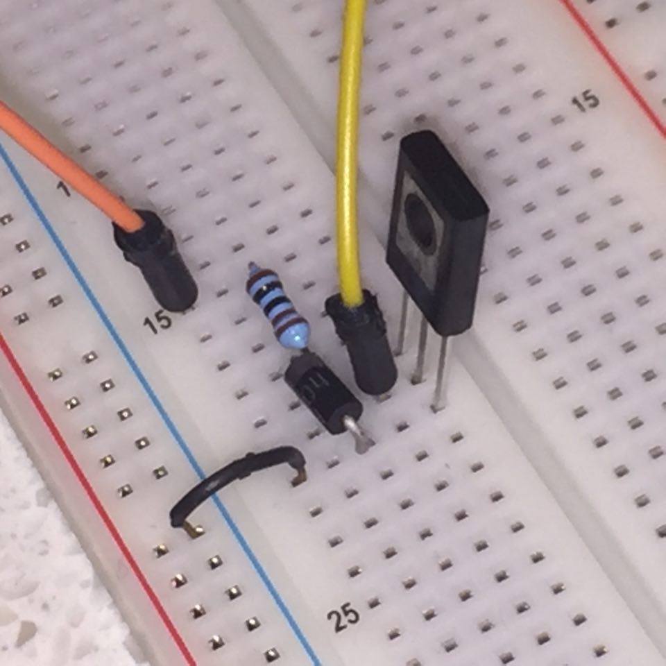
and speaking diodes.... you appear to be using a 1N4004 general purpose and you note you want motor speed control.
these are at odds with each other. the general purpose diode has a slow recovery time. PWM for motor speed control is very fast.

the purpose of the diode is to prevent back EMF from spiking your system due to the high voltage.
The motor will be spinning and act like a generator. using a diode will prevent that generated voltage or spike voltage from zapping your electronical bits.

however, pwm is very fast, the 4004 is very slow. you would be better to use a generic schottky that has twice the amps of the motor and about 10 times the voltage rating of your power supply.

about the transistor. a transistor requires power from the signal. is will use the amps input on the base and then allow a proportional amount of amps to pass from the collector to the emitter. your Darlington is very efficient and you only need a fraction of the amps in to get a large amount out.

the transistor is a Darlington pair witch means one transistor if being used to power on a second transistor. you have to power the first one and it will amplify the power to the base of the second one. this means you have to supply a much smaller current to your Darlington than if it were a single transistor. the transistor can be thought of as a current amplifier. you have to give it x amps it is will allow X times amps to pass.

Transistors can deliver power in proportion to the input. feed it a tiny bit, it will output a much larger value, but in proportion. this is called the linear range. if you feed is 0.01ma it might output 10ma, feed it 0.02 and it would output 20ma. when used in the linear range it acts like a resistor and can get HOT. most often, we use them as switches. for that we want to deliver more base current so that the output is well past the load requirements. this is called saturation and offers the lowest resistance, and that means although it is handling power and has some resistance, it will not get as hot as if it were being used in the linear range.

consider also that any current you apply to the base is then sent to the emitter. so it will be used. in one aspect, you can consider it a short to ground. if you connect an output pin from your arduino without a resistor, it could draw too much power and damage that pin. We do not want to just dump 20mA into it and we want to calculate the needed / desired current.

typically we say to drive a transistor into saturation hard. often twice the needed current. this is because as the transistor heats up, the values change and by the internal heating, and not driven hard into saturation, it can come back into the linear range and then act as a larger value resistor and start to self heat, failure of some sort ensues. either circuit failure or chip failure. you will find curves on the data sheet that help with this.

when someone says their transistor are getting really hot, my thoughts go to not driving it into saturation properly, or wrong selection of a part. a BJT has internal resistance and is a current amplifier. an FET does not consume current, but uses voltage. an FET has a MUCH lower internal resistance, so it can handle a much higher current without getting as hot.

that said, I would recommend you read up on transistors and how to properly feed them.
a note here is that the gain is hFE when used for a DC load. and using small letters, hfe is NOT the same.
hfe is for small signal current gain, think small letters, small power
hFE is for high current, and is what you want to use when using a transistor as a switch.

Thanks dave-in-nj for taking the time to explain these concepts , its very helpful and informative :slight_smile:

@OldSteve I have attached the new connection of the diode, would you kindly confirm if I have it the right way this time, I am not turning anything on just in case I got it wrong, I don't lose any of the parts due to back EMF.

You have it backwards. Just turn it the other way around.
The cathode is the end with the stripe. The cathode should be connected to the positive supply.
(As you have it now, the diode will short out the motor, only allowing it to receive 0.6V.)

Edit: I see that you still don't have a heatsink fitted. You'll need one. That's why your transistor is overheating.

Edit2: An N-channel MOSFET would be better.

is the diode getting warm? seems like it would just pass power when the motor has power, adding to the total load on the transistor.
Spidie, the idea is the diode blocks voltage under normal use. and if the motor were to run all the time, it would be totally unnecessary.
the diode is a safety valve that only acts when things are shut down and if there is a spike, it will give it a path, other than your chips.
the line (blocking) should be on the 5v side, not the ground side.
turn it around and see how hot the transistor gets.
use a small screw and washer or aluminum heat sink from something to add mass AFTER you test it with the diode in the correct way.