I'm noticing that the OP has not spoken since entry #3... so there is a lot of speculation here.
BabyGeezer:
if for example we wanted to 'limit' the ICE, might using a "high(ish)" resistor be the way to go ?
Yes, it might be a way to limit the collector current. ![]()
Once the transistor comes out of saturation, as MarkT explains, the collector voltage rises to something above the base voltage, about 0.7 V, so the power dissipation of the transistor is 0.7 times the collector current. For a BC337 without heatsink, this is 625 mW so you are strictly limited to less than one Amp. For a 2N2222 it is 500 mW and 670 mA and in any case you were limited to 800 mA.
But since the Hfe is quite variable, limiting collector current by fixing base current is a bad idea in the first place. ![]()
BabyGeezer:
if for example we wanted to 'limit' the ICE, might using a "high(ish)" resistor be the way to go ?let's say we wanted to "hold back" the motor from going full blast - or would that be better acheived by using a lower PWM duty cycle and not use the transistor in the 'active region' unnecessarily.
In most cases, when using a transistor for switching [whether a BiPolar, or a MOSFET, BTW], the goal is to keep the transistor in saturation, and out of the active region -- or, right on the edge of the active region & saturation, for faster switching. Most switching bi-polar transistor datasheets recommend biasing the transistor at a ß of, typically, 10 [though I've seen slightly higher, such as 15 or 20]. The point of that is to drive the Collector-Emitter voltage down, and achieve a trade off between drive current and low power dissipation.
Using the transistor active region to regulate power, is called a "Class-A" configuration -- and in some cases is a viable solution. But, it's the most inefficient way to do it, and only makes sense in low-power applications, or where very low distortion [i.e. linear transfer] & low noise are design goals [or a cheap and dirty design]. More often, especially when anything more than, say, a 1/2 watt, or so, of power is involved, PWM is the way to go. And, usually, a MOSFET does a better job.
HellasT:
A 220 Ohm resistor is needed when lower HFE transistors are used. Dont get me wrong, it will work but why push the arduino output to the limit ?
No, sorry, that's a myth. Hfe is irrelevant to saturation. In saturation the base-collector junction is forward biased and there is no conventional transistor action, just carrier diffusion from emitter to collector due to the carrier concentration gradient. Emitters are doped about 100 times more strongly than bases and bases about 100 times more than collectors, leading to a large concentration gradient which drives the action, not an electric field.
I suggest you go read a few datasheets on switching transistors which quote all the Vsat and related
values and graphs with "Ib = 0.1 Ic" or "Ib = 0.05 Ic"
If you set Ib = 5mA and try to switch 500mA, the Vce will rise to 1.5V or more, not the 0.1--0.2V of saturation.
That's 750mW dissipation compared to <100mW, ie scorching hot transistor v. cool transistor. To get high gain
the collector base junction has to be able to accelerate charge carriers clear of the base efficiently, which means the
collector has to be more positive than the base (for NPN). For efficiency in switching large currents the collector voltage has
to drop close to the emitter voltage.
Paul__B:
What limit? 4.35 V over 220 Ohm is 20 mA, a common current used to illuminate LEDs brightly. Nowhere near the absolute maximum rating which I do not even mean to cite - since doing so tends to lead foolish people to fantasise that is an acceptable target to use.
So you didn't read MarkT's explanation?(I have to chuckle here. "most diagrams" - on "Instructables" perchance?
)
Oh, so you do have some knowledge about "saturation mode" in which Hfe is irrelevant, so why do you talk about "high HFE transistors"? Mark has explained that you need at least 5% of the collector current, that is, a gain of 20 at best for saturation.So your 1k resistor feeding 4.35 mA to the transistor base can hold it in saturation for no more than 87 mA.
I do not understand the attitude. Did i offend you in some way?
You are pointing out my mistake and thank you for that but for real why this attitude?
P.S.
you are also right about the fact that 20ma is perfectly ok from the arduino output. I forgot because i am used to working with other MCU's that can not handle that much.
MarkT:
No, sorry, that's a myth. Hfe is irrelevant to saturation. In saturation the base-collector junction is forward biased and there is no conventional transistor action, just carrier diffusion from emitter to collector due to the carrier concentration gradient. Emitters are doped about 100 times more strongly than bases and bases about 100 times more than collectors, leading to a large concentration gradient which drives the action, not an electric field.
I suggest you go read a few datasheets on switching transistors which quote all the Vsat and related
values and graphs with "Ib = 0.1 Ic" or "Ib = 0.05 Ic"
Agreed. I will dig into it. Thank you.
Reading "attitude" into forum postings is dangerous indeed. If you say something inappropriate, it will be challenged, not merely for your benefit, but for the presumed benefit of others who may stumble across the given thread in their own search.
A teaching principle which was emphasised in the lectures I attended on the weekend is to require the "student" to think in detail about the consequences of their suppositions.
This discussion has had a number of contributors; some people with good ideas, some who do not understand the matter of bipolar transistor behaviour. MarkT generally comes in to explain it; I may get in earlier - we are obviously in different time zones, there is a bit of "to and fro" here, I am most unlikely to repeat something he has comprehensively explained.
O.P. has gone maybe. What sort of transistor? Mosfet? Logic level?
I am on HellasT's side:
20mA may be perfectly safe for a single pin but it is not the only limit. The whole ATMega has absolute maximum rating 200mA and there are the strange limits of total current for groups of pins. Also sourcing/sinking unnecessary current may cause voltage droop of ATMega's power rails which may affect i.e. ADC precision. Not speaking about efficiency.
For reference let's look into a datasheet of NPN BC337 already mentioned in this discussion (link in post #21). There is "Saturation Region" figure:
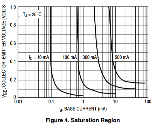
You can get more information about the saturation characteristics from it. For example for 100mA collector current the V_CE is quickly decreasing with increasing base current until about 2mA (Ic/Ib = 50). For higher base current the V_CE is decreasing only slightly - probably not worth the increased base current and surely nothing that will cause a "scorching hot transistor". For higher collector current it is a bit worse - you need about 20mA base current for 500mA collector current - still gain of 25. And those numbers are probably for the "poorest" -16 selection. The "better" -25 and -40 selections should have better results according the Nexperia's more detailed datasheet. If interested, study Figures 10-12 closely.
I believe the Ic/Ib = 10 value is for historical reasons - transistor is considered "in saturation" when Ic/Ib = 10. But this does not mean you MUST use this ratio to get optimal results. Old transistors probably really needed such high base current. But as you can see it is not absolutely necessary with "modern" transistors, exactly as HallasT have said.
Also note the numbers are @25°C. Since too low base current -> hot transistor -> better gain -> lesser base current needed, the temperature rise is self-limiting for reasonably low base currents.
Since theory and comparing numbers from datasheets may be misleading I did a quick and dirty real life test. I connected the collector of a BC337-40 to a constant current source of 126mA, varied the base current and measured V_CE. There are results:
Ib -> V_CE
12 mA -> 60mV
3.6 mA -> 80mV
1 mA -> 140mV
0.4mA -> more than 1 V (limited not to damage the transistor)
You see that at 1mA base current, less 1% of collector current, the voltage drop is still reasonable - but you cannot go much lower.
Smajdalf:
20mA may be perfectly safe for a single pin but it is not the only limit. The whole ATMega has absolute maximum rating 200mA and there are the strange limits of total current for groups of pins.
Good point. If one wants to use 10 more outputs then there may be a problem. If not then it should be fine.