I wrote a sketch to monitor a pair of REED switches, 1 trips to LOW when a linear actuator (that drives a piston water pump) reaches max extension, the other goes low when the actuator retracts. My sketch compares the switches status and then biases a darlington (TIP120) base accordingly to cycle the actuator through its range of motion.
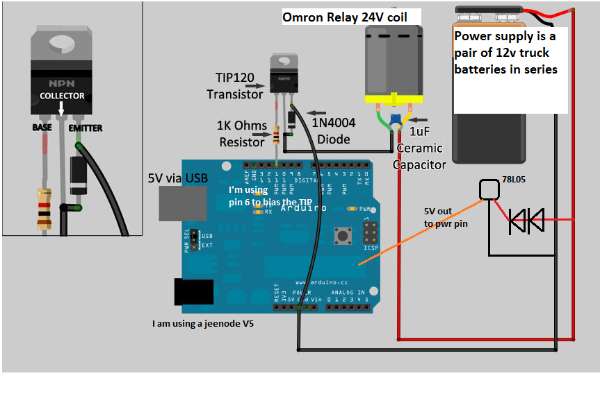
I cross wired an Omron 24VDC coil relay to switch polarity ...hooked up a 4 amp 24 volt power supply and the system seemed to work just fine. The relay coil switched on and off in accordance with the position of the actuator (fitted with a magnet on the end). I checked for polarity switching with a DMM and it all looked great. 24 VDC was applied across the com contacts and I measured 24 or -24 V depending on the coil status.
So then I attached the actuator motor to the NO contacts of the relay. Now the "Extended" REED switch failed to turn the coil on in time...the actuator ran to the end of its travel (something the mfr says not to allow). I found that it takes many seconds for the TIP to pass enough current to trip the coil. Eventually it does but I can't understand why it takes so long.
I tried using limit switches that I know are good but same problem. Also tried using a larger 24 V 4 amp PS ...the motor only draws 0.4 amp. I've got a blue cap across the coil contacts and a diode although this relay is pre-fitted with them.
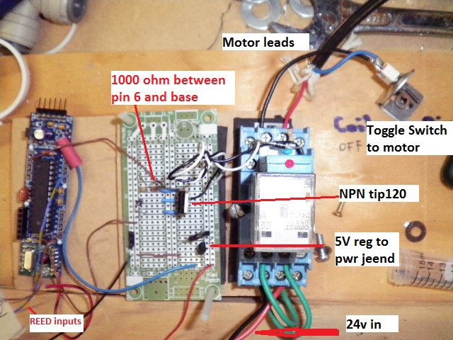
I have made a few successful projects now using TIP120/PWM pin to control things...I've got a 1000 ohm resistor between the pwm and the base.
I'm powering the Jeenode with a 78L05...I put a pair of diodes between the 24V supply and the input pin just to give a bit of voltage drop from the 24 volts (although it is rated to 35 volts). Measure 4.9 volts out to the jeenode.
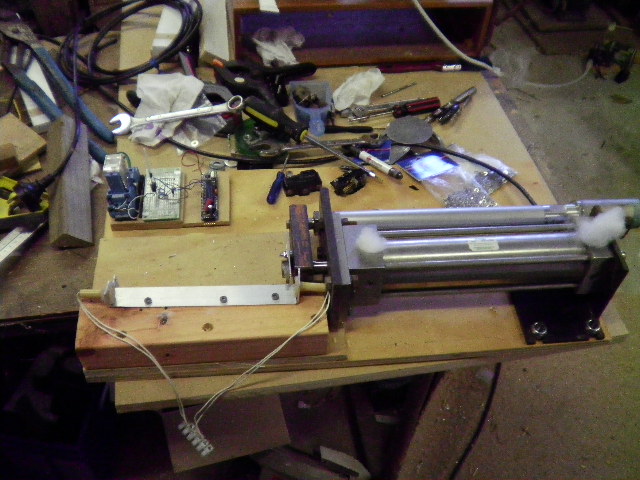
I'm at a loss...any advice or suggestions on how to debug would be great. Attached are my sketch and a photo of my "driver" and homemade pump (using a stainless steel pneumatic ram, check valves not yet installed).
EDIT: I thought i attached the sketch...here it is in case it helps:
/* Describe: Driver for low a low speed positive displacement water pump
Saved to: Documents\farmstuff\Arduino\WATER
*/
// Make DIO pin assignments
#define ExtendedReedPin 4 //DIO1, port 1 DIO on the Jeenode
#define RetractedReedPin 5 //DIO2 on the Jeenode
int TIP120pin = 6; // this is DIO3 (this is a pwm pin)
//Variables that will change
int ExtendedState = 0; //Current state of the Extended Reed Switch
int RetractedState = 0;
int OutState = 0;
void setup () {
Serial.begin(9600);
pinMode(ExtendedReedPin, INPUT_PULLUP); // initialize the DIO as inputs or outputs
pinMode(RetractedReedPin, INPUT_PULLUP);
pinMode(TIP120pin, OUTPUT);
if (ExtendedState == HIGH && RetractedState == HIGH) {
analogWrite (TIP120pin,255); // analogWrite only applies to pwm pins
}
}
void loop () {
//analogWrite (TIP120pin,0);
Serial.print (OutState); // all of the serial.prints are for debugging
Serial.println(TIP120pin);
delay(50);
//READ Reed switches: open or closed:
ExtendedState = digitalRead(ExtendedReedPin);
RetractedState = digitalRead(RetractedReedPin);
if (ExtendedState == LOW && RetractedState == HIGH) {
//digitalWrite(OutState,LOW); // This does not work
analogWrite (TIP120pin,0); // this does
}
if (ExtendedState == HIGH && RetractedState == LOW) {
analogWrite (TIP120pin,255);
OutState = digitalRead(TIP120pin);
}
Serial.print ("ExtendedState = ");
Serial.print (ExtendedState);
Serial.print (" RetractedState = ");
Serial.print (RetractedState);
Serial.print (" Output to TIP120 = ");
Serial.println(OutState);
}