These guys claim their ducted system generates 50% more power than non-ducted. Your increase in performance would be somewhere between 0% and 50%. Would look cool, in any case.
Search term for more ideas: ducted wind turbine
Edit to add: I would try a much larger shroud (relative to the fan diameter) than that shown in the photo. Something like this:
The reason larger ones aren't used in real life probably has to do with the tremendous increase in drag and resulting high loads on the tower and foundation.
Also, very simplistically:
Power (W) = 1/2 x ρ x A x v3
Power = Watts
ρ (rho, a Greek letter) = density of the air in kg/m3
A = cross-sectional area of the wind in m2
v = velocity of the wind in m/s
So if you double the wind speed, the power produced will go up approximately eight times (at best).
Before you build the complete circuit, to see if the LED is bright enough, add your selected LED to a 470R resistor (don't use less than 220R).
Increase the resistor value until the LED is too dim.
Lets' say 1K was too dim.
Select a resistor about half way in between 470R and 1k; 680R, check brightness.
Add one LED/resistor pair to the following circuit to see if the circuit works.
Your motor leads might need to be reversed.
If it works, add several more component pairs, the transistor should not get hot when the LEDs are on (warm is okay).
* If it does get too hot, let us know.
Mine was actually one of them
And looking back through the lengthening thread it is essentially similar to that from @gilshultz in post #13. IOW, forget trying to switch on your LEDs from the small and noisy ouput from a DC motor. Why are you apparently fixated on that approach?
Emulation in the current context is 'benign deception', yes? As I understand it, the proposed presentation by your daughter (fronting for you and this forum) is to flick a switch and show a fan representing a wind turbine power up, followed within a short but so far unspecified time apparently powering six LEDs (mains lights) fora small community. The suggestion I made in post #11 would do that. Please advise before I spend time drawing the schematic for that, if needed.
Haven't heard back from my post #25 - time zone I guess? Anyway meanwhile decided it was quicker to breadboard and test the circuit I suggested. I suspect the discussion could othewise go on for a long time!
I really appreciate everyone's input. @jim-p I'm not ignoring your questions. However, my inexperience does not allow me to respond. I've put few circuits together over the past few years - nothing major - my most recent one being a text notification when my motorcycle detects a shift in inclination after a 5 seconds timer (anti-theft experiment). However, with time I can order all the components online and never bother to source locally, as we don't really have a fully supplied electronics store around here. Hence, without being told "you need components A, B, C..." I wouldn't be able to call around and see what if the needed parts are available around. I hope you can appreciate error loop here (I can't tell you what is around because I don't know what I can possibly need to call the stores to specifically ask for the parts...)
@Terrypin I hope you don't think I'm wasting your and everyone else's time. If all fails, this thread has been, believe it or not, a good learning experience I can share with my older kid. Thank you so much for the board picture, would make it so much easier to recreate (so we don't underestimate my newbieness, a pic from the other angle would also help). So if I can follow correctly, these are the parts I need (✓ means I have it already. "Do not have" I have to call around for):
1 DC Motor (is 3-7v ok?) ✓
1 2 pin switch (I also have illuminated switches to avoid the extra LED) ✓
6 LED diodes (I'll use all green or red for simplicity) ✓
1 10k 1/4w resistor ✓
1 56k 1/4w resistor (I have 10K, 22K, 47k, 100k resistor, can I use the 100? Use a 10K and 47K in series?)
1 3k3 (do not have)
1 diode (junction I assume from upper right in diagram). How should I ask for it? (do not have)
1 470uf (what voltage I need?) (do not have)
1 NPN transistor (Do not have. Any specifics required when calling? Where is that on your board?)
What is the circular symbol in the upper right?
What is a snubber diode? What specific component I can ask for at the store?
Is the ground simply offering reference to the gnd wire or do the girls need to ground it?
Where is motor on the schematic?
It is indeed! However, I can supply 5V with my power supply at home, but the girls at school will have to use 4.5v (3 AA or AAA batteries). Will it still work or do I need to calculate resistance?
It wasn't clear to me whether you wanted me to perform trial and errors on circuit in regards to resistors. I wanted to keep it as simple, with the least failure points as possible. I won't be there to troubleshoot with the girls if something burns up in the middle of their presentation(s). I assume they will be playing with it and showing it to the school on the presentation day (it is a school presentation, not just to the class). Keeping the circuit in parallel may give them assurance that if some points fail, they may still have lights in other areas.
For a battery of 4.5V, you might need to change 100R to 120R.
470R will probably be fine for the LEDs, you could try 220R to see the results too.
What’s nice about this circuit is the faster the fan spins, the LEDs become on more solid.
This gives the audience feet back if they blow on the fan blades.
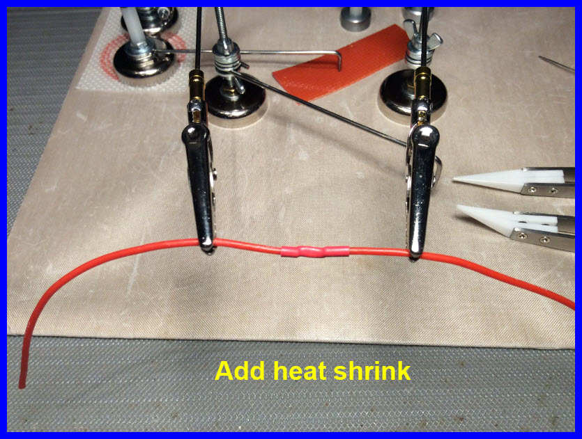
The method of making the LED and resistor combination is self explanatory.
Add heat shrink to cover the resistor and LED leads.
Of course, there are wires soldered, not shown, solder the wires before you solder the resistor, make good soldering joints.
No fan turning, no battery current is consumed. (well may be 5mA)
Yes; I used a button but a switch might be better; its position indicates ON or OFF, so my large red LED not needed, unless as a cosmetic . EDIT Wait, button rules; allows the interaction I described.
All are 1/4W resistors.
I'm sure any from 1k to say 4k7 would be OK. As I said, trial and error. You have 10 days until your deadline of 17th May. It's beginning to sound as if this is a one-
off project? If however you plan to resume your electronics, perhaps with Arduino too, you need to get a decent range of components? And do some reading on basic electronics.
Google 'diodes' and 'snubber' and 'flyback' and do some reading!
and
Eh?! It's spelt out on my schematic: "Small DC motor with propeller emulating wind turbine. Snubber (‘Flyback') diode in parallel."
This is all very good info. Thank you both. And about sliding the heat sleeve before soldering, I disagree with LarryD. I've missed to perform that more than once, and I still haven't learnt...
I've found a 220uf and 2N2222 (hopefully 25v is better than 16v for this project) so I'll try LarryD's suggestion first as it requires less components. I'll give you some feedback tomorrow.
@larryD please bear with my complete neophyte lack of pertinent knowledge. Before I power this thing and start testing pair by pair of LEDs as you suggested. Is this the right setup as per your schematics?
2N2222 is on row 28 (emitter),29 (base),30 (collector)
220uf is on 28 (negative), 26 (positive)
Nothing is touching anything. Sorry for all the exposed wires
I assume the supply goes to the other cable of the switch and to the negative of the board on the far right.