ok guys so my goal is to use an arduino with a mosfet to control a motor.
with 2 switches For an airsoft RIF
Switch 1 /trigger 1
Switch 2 /trigger 2
so i want to press say switch one to make the motor do spin once.
if i press switch two it will spin say 2 times./
the code is not the problem, its the wiring im having problems with, im planning to use a pre made mosfet the Pico SSR 3. that has
1 trigger contact-
1 motor -
1 battery -
how would i go about controlling this with an arduino, i have tried to make a mosfet myself and it kindof worked but i was frying them , so i want to use this pre made one. i have no basic electronic knowledge, so if anyone could help me getting power to the arduino is no issue, i just need help with the wiring.
i'm surprised i couldn't find a schematic for the Airsoft PicoSSR
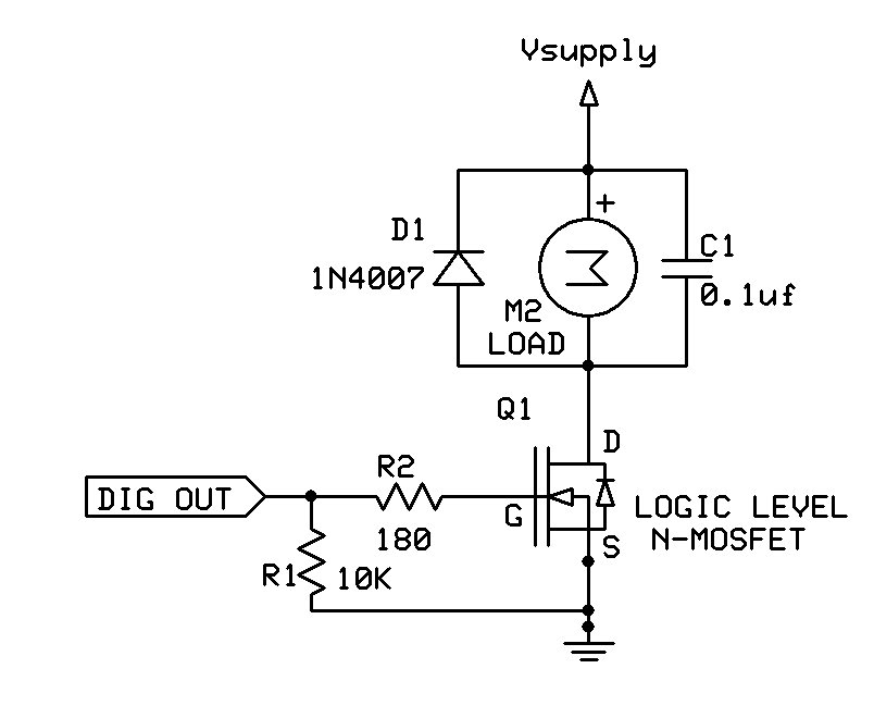
the schematic below shows common use of a mosfet to drive a motor. the diode across the motor provides a path for current when motor is turned off. that current can create high voltages.
The mosfet connects the motor to ground. (which i believe you show). A 10k resistor is often between the gate and source to deplete any residual charge on the gate so that the mosfet turns fully off. connecting an Arduino digital output to the gate and setting it HIGH should make the mosfet conduct and drive the motor.
mosfet resistance is often measured in milliOhm, meaning that a mosfet needs to dissipate very little power when passing relatively large currents. wondering how you did to "fryed" them. (diode?)
it looks like you're diagram is correct. maybe before testing with a motor, use and LED and 1k resistor.
isn't it true that as long as the gate voltage is above the source voltage, the mosfet will conduct?
No. The gate voltage has to be far enough above the source voltage for that device. For most MOSFETs that's 10 to 12V.
A logic-level MOSFET is designed to be fully on with only 5V or so. Unless the device is fully on it will have more resistance and could overheat. The actual voltages vary significantly between lots due to manufacturing spread too, so its best not to push your luck.
Beware of the threshold voltage rating - its not relevant to using a MOSFET as a switch.
if the mosfet is connected between the motor and ground, the drain is ~1V above ground. why would the gate need to be above both the source and the drain voltage (you said 10-12V)?
on the other had, if the mosfet were between the supply voltage (e.g. 12V) and the motor and the gate set to the supply voltage, then the source would be slightly below the supply voltage.
i had never heard of a logic level mosfet. thanks for bringing it up.
the datasheet for the STP80NE06-10 specifies that its gate threshold voltage (Vgs) is between 2-4 V. seems like it should work in most cases with a 5V output.
this has a pretty low Rds (< 0.01) very high current (80A). probably targeted for a high current application requiring a higher Vgs to achieve that resistance. I would guess that it would still turn on at a lower gate voltage but with a higher Rds.
guess i've never had a problem is the mosfet that had a gate threshold voltage that was higher than what I was driving it with and had a higher Rds than I could work with..
gcjr:
i had never heard of a logic level mosfet. thanks for bringing it up.
the datasheet for the STP80NE06-10 specifies that its gate threshold voltage (Vgs) is between 2-4 V. seems like it should work in most cases with a 5V output.
You might think that, you'd be completely wrong.
2--4V threshold voltage is a red flag saying NOT LOGIC LEVEL. Typical threshold voltages for logic level FETs are 0.5--1.0V. If the threshold voltage can be as high as 4V, that means the device is fully off below 4V. No way can it be fully on at 4.5V if that's the case. Logic-level FETs need to be fully on at 4.5V nominal (meaning 5V allowing for supply variation)
this has a pretty low Rds (< 0.01) very high current (80A). probably targeted for a high current application requiring a higher Vgs to achieve that resistance. I would guess that it would still turn on at a lower gate voltage but with a higher Rds.
Unless you are going to water-cool the FET, ignore the current rating. Go by the power dissipation being I-squared-Ron
At a lower gate voltage the channel is not necessarily formed at all, just a weak-inversion layer.
guess i've never had a problem is the mosfet that had a gate threshold voltage that was higher than what I was driving it with and had a higher Rds than I could work with..
this is all very interesting and I understand that there are subtleties to this that I don't understand. i appreciate the comments
gcjr:
I would guess that it would still turn on at a lower gate voltage but with a higher Rds.
i used a mtb40b10e (40A 100V) to drive a small 12V DC motor and it seemed to work with the gate at 5V (i.e. it was more on than off).
No way can it be fully on at 4.5V if that's the case.
does it need to be if you're driving a small motor that draws maybe 200 ma? the chart above indicates it can pass 10A at 5V.
of course this is not an ideal part for what i'm doing and your comments are making me appreciate that I should find better parts. I am interested in part numbers for mosfets, or maybe just fets that at adequate for the small motors i'm using and can be used for braking.
hey guys so i got the mosfet and wired it all up how i have in the picture. if i use a led, the code works fine, turns on then off in "semi" and in "full auto" it blinks on and off, this is what is suppose to happen,
now when i connect the motor on semi it acts like a normal switch? when i press it in the motor runs intill i lift of the button, when i press the full auto button down it pulse's like it should, what could the cause be?
int DWELL = 20; // how long to open MOSFET ms
int RATE = 30; // how long to wait after closing MOSFET ms
int MOSFET = A0; // MOSFET control pin
int SEMI = A4; // semi auto switch pin
int FULLAUTO = A5; // full auto switch pin
int FULLAUTO2 = A3; // full auto switch pin
int SEMISTATE = LOW; // start state of semi switch
int SEMISTATUS = LOW; // current state of semi switch

void setup()
{
  pinMode( MOSFET, OUTPUT ); // MOSFET
  pinMode( SEMI, INPUT_PULLUP ); // Semi Auto
  pinMode( FULLAUTO, INPUT_PULLUP ); // Full Auto

}

void loop()
{

  SEMISTATE = digitalRead( SEMI ); // read current status of semi switch

  if( SEMISTATUS != SEMISTATE ) // not the same as last / start status (must be LOW)
  {

    if( SEMISTATE == LOW ) { // switch is closed

      semiAuto(); // fire semi auto shot

    }

    delay( 50 ); // wait to prevent the switch bouncing

    SEMISTATUS = SEMISTATE; // set current state to current trigger state

  }


  if( digitalRead( FULLAUTO ) == LOW ) // full auto switch is closed
  {
digitalWrite(LED_BUILTIN, HIGH);
    fullAuto(); // fire full auto

  }

}

void semiAuto()
{

  digitalWrite( MOSFET, HIGH ); // open MOSFET

  delay( DWELL ); // wait to clear barrel

  digitalWrite( MOSFET, LOW ); // close MOSFET

}

void fullAuto()
{
digitalWrite(LED_BUILTIN, HIGH);
  digitalWrite( MOSFET, HIGH ); // open MOSFET

  delay( DWELL ); // wait to clear barrel

  digitalWrite( MOSFET, LOW ); // close MOSFET

  delay( RATE ); // wait for next shot

  if( digitalRead( FULLAUTO ) == LOW ) // if trigger is still pulled
  {

    fullAuto(); // call function again

  }

}
Could be power related or EMI related - switching big currents is prone to induce spikes into nearby wiring and/or knock the supply voltage down briefly. The LED shows the sketch is programmed OK, so it must be a hardware issue.
so i can get it to turn on and off with a delay with this code:
int DWELL = 10; // how long to open MOSFET ms
int RATE = 8000; // how long to wait after closing MOSFET ms
int MOSFET = A0; // MOSFET control pin
int SEMI = A4; // semi auto switch pin
int FULLAUTO = A5; // full auto switch pin
int SEMISTATE = LOW; // start state of semi switch
int SEMISTATUS = LOW; // current state of semi switch
////////////////////////////////////////////////////////////////////


////////////////////////////////////////////////////////////////////

void setup() {
  // put your setup code here, to run once:
pinMode( MOSFET, OUTPUT ); // MOSFET
  pinMode( SEMI, INPUT_PULLUP ); // Semi Auto
  pinMode( FULLAUTO, INPUT_PULLUP ); // Full Auto

}
////////////////////////////////////////////////////////////////////

////////////////////////////////////////////////////////////////////
void loop()
{

digitalWrite(LED_BUILTIN, HIGH);
  digitalWrite( MOSFET, HIGH ) ; // open MOSFET

  delay( RATE ); // wait to clear barrel

  digitalWrite( MOSFET, LOW ),delay( DWELL) ; // close MOSFET

  }


////////////////////////////////////////////////////////////////////