Background
This might get a little long but I want to provide details on what I have tried as I have definitely been trying for months now. I have had great success with the ATMEGA328P but was looking for something with more power and memory so decided to give the ATMEGA1284P a try out!
What I have tried
I have largely been following this helpful article: ATMEGA1284 Article
I built both the bootloader circuit and the serial circuit into one single circuit board. The idea is that I can flash the bootloader on, switch the connection, upload a sketch (like Blink) to test with the built in LED. The exact circuit I have created is shown below:

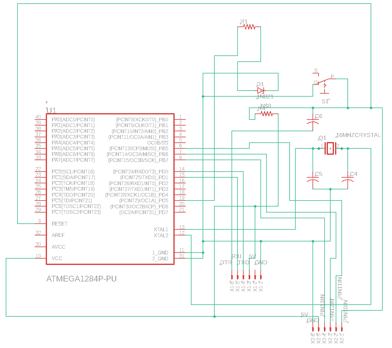
Anyone is welcome to use it if we can solve what is wrong in my problem..
This helps ensure that the connections are solid and much more repeatable for testing. Next I have tried to install a bootloader. Since I have an Arduino Uno R3, I plug it in as the article shows, with my circuit I created.
First Issue
When using the "maniacbug Mighty 1284p 16MHz using Optiboot" bootloader, I place it into the hardware folder as recommended:

When selecting this as my bootloader, the "Programmer" option disappears:
For this reason I trialed "Goldilocks 20MHZ" which does have the "Programmer" show up:

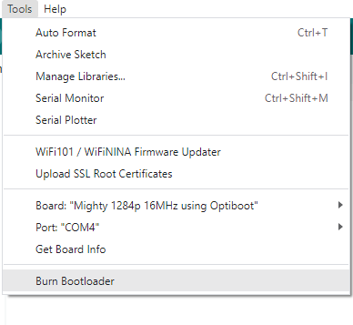
Selecting Programmer = Arduino as ISP, the port, and Goldilocks 20MHZ, I click burn bootloader and it tells me success!

Interestingly enough, if my reset switch is turned to on, it won't burn the bootloader successfully. I only say this as this is my only proof that something is recognized but I will get to that..
Now if I try to swap the pins and use my FTDI USB-to-serial converter board (same as the one from the article), I try to upload the blink sketch (modified to use pin 19):

Arduino IDE says "Uploading" for a long time but eventually comes back with the errors:

What to try next?
I know this is a lot to go through, but I am at a loss for what to try next. I would love to successfully get a sketch to upload correctly of any kind of course. I thank you in advance for anyone who helps!

