Trouble porting LoRa+Nano project to Attiny85 (Serial Comm Issue?)

Hello,

I recently made a simple LoRa remote control. This remote control would use an Arduino Nano to send out a serial command via a Reyax RYLR896 LoRa module that would transmit to a receiver. Pressing a button on the remote control would turn on an LED on the receiver. Very simple, worked flawlessly.

I have since attempted to remove the Arduino Nano from the remote control side and move the entire project over to an Atmel Tiny85 (I THINK this is the same as the Attiny85). Aside from changing the GPIO pins, the code remains essentually unchanged. Unfortunately, it does not work.

Pressing the button on the remote works, as the "transmit led" on the remote flashes, letting me know that the button has indeed been pushed and detected, however the LoRa singal is not transmitting. I've never used the Software Serial library on one of these Attiny chips before, so it's possible that one of my settings is incorrect and would appreciate any advice.

NOTE: This code DOES compile and upload to the Attiny chip.

Transmitter Code:

#include <SoftwareSerial.h>

#define transLed 4
#define recLed 3
#define Rx 2
#define Tx 1
#define button 0

SoftwareSerial LoraSerial(Rx, Tx);

String incomingString;
int oldState, newState, state = 0;

const unsigned long ackTime = 5000;
//unsigned long previousTime = 0;
unsigned long timerStart = 0;
bool ack = true;

void setup() {
  pinMode(transLed, OUTPUT);
  pinMode(recLed, OUTPUT);
  pinMode(button, INPUT);

  //Serial.begin(9600); // Serial Terminal
  LoraSerial.begin(9600); // LoRa COMMS

}

void loop() {

  //unsigned long currentTime = millis();  
    
  // Send a message to Receiver when button is pushed
  if(digitalRead(button) == HIGH){
    if(state == 0){
      LoraSerial.println("AT+SEND=715,1,H");
      //Serial.println("H");
      state = 1;
      timerStart = millis();
      ack = false;
    }
    else {
      LoraSerial.println("AT+SEND=715,1,L");
      //Serial.println("L");
      state = 0;
      timerStart = millis();
      ack = false;
    }
    digitalWrite(transLed, HIGH);
    delay(250);  
    digitalWrite(transLed, LOW);
  }

  // Flash an LED if Acknowledgement is received from Receiver
  if(LoraSerial.available()){
    incomingString = LoraSerial.readString();

    if(incomingString.indexOf("A") > 0){
      //Serial.println("Acknowledged!");
      ack = true;
      digitalWrite(recLed, HIGH);
      delay(250);
      digitalWrite(recLed, LOW);
    }
  }

  if((!ack) && (millis() - timerStart >= ackTime)){

    // Blink LEDs
    digitalWrite(transLed, HIGH);
    digitalWrite(recLed, HIGH);
    delay(100);
    digitalWrite(transLed, LOW);
    digitalWrite(recLed, LOW);
    delay(100);
    digitalWrite(transLed, HIGH);
    digitalWrite(recLed, HIGH);
    delay(100);
    digitalWrite(transLed, LOW);
    digitalWrite(recLed, LOW);
    delay(100);
    digitalWrite(transLed, HIGH);
    digitalWrite(recLed, HIGH);
    delay(100);
    digitalWrite(transLed, LOW);
    digitalWrite(recLed, LOW);
    delay(100);

    state = !state;

    ack = true;
    timerStart = 0;
    //Serial.println("Ack FAIL");
  }

}

NOTE: I've commented out the sections of code that are meant to print a messages to the serial console. I did this, just in case the Attiny85 cannot handle multiple serial lines.

THINGS TO CONSIDER

  1. Is the clock source set correctly? I've seen conflicting details on what frequency the internal clock should be set to on Attiny chips when transmitting serial data. I've tried both 1MHz and 8MHz, unsuccessfully.

  2. Does the baud rate matter? For the initial project, I had the baud rate set (on both the Arduinos and the LoRa Modules) to 9600, which worked fine. I've seen some reports that the Attiny chips work best with 38400. I've tried both, to no avail.

  3. Can this Attiny85 source the correct current to transmit data via the LoRa Module? I recognize that the Arduino Nano that I used initially would trasmit serial data at 5V. I'm unsure what this Attiny transmits at. I am powering it with 5V and I believe the GPIOs that flash the LEDs only supply 2 Volts. I'm unsure if this matters.

  4. I'm using a voltage divider to power the LoRa Module as the Attiny operates at 5V but the LoRa module operates at only 3.3V. One thing I noticed is that, when I remove the LoRa module, the voltage across the Vcc and Gnd are roughly 3.3V, however when I plug back in the module, my meter only reads ~2V. This is a bit strange to me, but that could also mean that the forward voltage drop of the module is 1.3V. Am I supplying enough power?

  5. Are the pins that I am using to transmit data acceptable? Again, I'm not super familiar with these Attiny chips but have seen nothing to indicate that specific pins need to be used for RX and TX.

Unless there's something else, those are all of my ideas. Please let me know if I need to clarify any details and/or if any additional information is needs. I can post details about the circuit diagram, however I've quadruple-checked everything and I don't believe there are any faults in the wiring. I've be happy to be proven wrong.

Thank you all in advance for your advice and knowledge.

Best,
Joe
It is a bad idea to use String objects on any AVR based Arduino, as they cause memory problems and program crashes, and especially bad on such a limited chip as an ATtiny.

2 Likes

Thank you. What would you suggest as an alternative?

As the most sensible alternative to Strings, use the routines in the C-string library.

One of many online introductions to <string.h>.

Note that input/output routines like printf(), scanf(), etc. are not implemented for most Arduinos, but there are simple ways to get around that limitation. I strongly recommend to study the Serial Input Basics tutorial.

Could you post a drawing of your circuit?

My understanding is the ATTiny85 has no hardware serial peripheral, so software serial is the only option.

Can you say how you are programming the 85? Are you using a separate programmer or Arduino as ISP, or are you connecting directly via USB?

I don't think you can power the Lora module with a voltage divider. Did you do that when it was a Nano circuit? Anyway, if you can post your schematic, we can see how you have it set up.

Edit: Forgot to say, the correct processor speed to select is the one that makes the Blink example sketch blink at the right speed.

Sherman,

Thank you so much for commenting.

I was just about to draw up a circuit diagram for you, but I tried something first. That is, I added a second Voltage regulator to power the LoRa module. This worked. I can now transmit data from the remote control to the receiver and turn on my LED.

HOWEVER, for some reason, I'm unable to receive data back from the receiver. In my firmware, I created an asynchronous acknowledgement so that I could be notified (via an LED on the remote) if my signal was received. And while I've confirmed that my receiver is transmitting the acknowledgement back, the remote isn't receiving it.

NOTE: To test, I had the receiver running normally and transmitted serial commands manually with my FTDI programmer and the remote control's LoRa module. Via the Serial Console, I was able to send my commands, turn on the LED on the receiver, and then receive back the acknowledgement, which printed in the serial console. So the logic works fine and the modules are seemingly working correctly.

I tested the continuity between the TX pin on the module and the RX pin on the Attiny85 and it seems to be fine. Could this be an issue with the baudrate? Everything is currently set to 9600.

To answer your other questions:
*Correct, I'm using the SoftwareSerial library

*I'm programming the Attiny85 using the Arduino IDE and using an Arduino Nano as ISP.

*For the initial Nano circuit, I was using the 3.3V pin to power the module. For the current "tiny circuit", I WAS using a voltage divider to drop the regulated 5V signal down to 3.3V, which did not work. As I mentioned above, adding a second voltage regulator (3.3v) has seemingly fixed the power issue, which seems to have been my primary/main issue.

*Just to close the loop here, the LEDs blink correctly when programming with the internal clock set to 1MHz. That's how the current setup is programmed. Again, everything is working except for receiving the acknowledgement

Best,
Joe

EDIT 1 I just realized that I never setup the RX pin on the Attiny85 as an input :thinking: That being said, I never did with the Nano either and it worked fine. I'll try that. Wouldn't that be funny...
EDIT 2 It was not the pinMode() :confused:

I know you think you've described your system accurately, but I am unable to picture it without a drawing. Maybe someone else can help figure out the ack signal. But I should say that I've just told you everything I know about Lora. So the drawing might or might not help.

Sherman,

I understand.

My only thing is that the line from TX pin on the module to the assigned Software Serial RX pin on the Attiny is just a single jumper. There are no other passive components in series or parallel with the connection. Everything else is working fine, including two indicator LEDs and the input button; so I don't believe it's a wiring issue. Additionally, the module is transmitting properly, so it's not as though I have the RX and TX lines swapped.

I think now that the issue is limited to the following:

  1. The Attiny85 cannot read serial communication from pin 2. I've not seen anything online to indicate this.
  2. The baude rate is set incorrectly and therefore interferring with how the Attiny85 reads serial communication.
  3. The 3.3v serial signal coming from the LoRa module is not compatible with the Attiny85. Perhaps a resistor or voltage divider needs to be added. This just popped into my head as I was typing so I will continue my investigation here :bulb:
  4. Some other programming/processing factor that I'm not aware of.

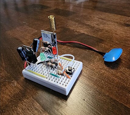
If you want, I can post a picture of the remote in the meantime :grimacing: Sorry I'm being lazy with the schematic, I just don't think it's a worthwhile endeavor at this point.

Regards,
Joe

I don't think the 3.3V vs 5V thing is the problem. If the Lora module is actually sending 3.3V, the Nano will recognize that as High. So there shouldn't be any need for voltage translation.

I think the first thing is to determine if something is being sent at all. I assume you don't have a scope, but do you have an LED you could rig up on that line? You could connect the high side of the LED to 3.3V through a resistor, and the low side to the line. Then if the line goes low for traffic, the LED will flash. I'm assuming that line idles in the high state, which you can confirm with your multimeter.

Otherwise, I just don't know anything about Lora or really the 85, so I don't know how the baud rate is set. Well, software serial presumably lets you set the baud rate on the receive side, but I don't know how Lora handles that on transmit.

Sherman,

After doing some digging, the Attiny should be able to receive serial communication between 1.8V and 5.5V, so that shouldn't be a problem.

I DO have a scope and could see the RX line drop appropriately. And only when the receiver was powered on (just to rule out any false positives), indicating that the acknowledgement was received by the remote control's LoRa module. And that's correct, the line idles HIGH.

Both of the LoRa modules have their baud rates set with AT commands and are both set to 9600, matching the SoftwareSerial objects on each controller.

It's as though the serial data is just hitting a brick wall at the IC pin. It's quite frustrating.

All that's really left to test is various baud rates and possibly a different set of Rx/Tx pins on the Attiny.

Otherwise, I'm out of ideas :confused:

Why don't you try loosening up this test:

if(incomingString.indexOf("A") > 0)

to just see if anything is received at all.

And what exactly are you expecting to receive? Which characters? I'm just wondering why it's ">0". Is this a unicode thing?

Edit: If you have a scope, then you should be able to confirm the sending baud rate. At 9600 baud, each character should take about 1ms.

Edit2: If you set up both sides at 9600, and the initial transmission works, then it should be right coming back the other way. And if the initial transmission works, I think that means you have the right processor speed selected for the 85. So I don't know why it wouldn't work. Maybe it's a pin numbering issue. I think we need an ATtiny85 expert.

Edit3: I would try selecting 8MHz as the processor speed if you haven't already. Actually, if you set up your Arduino as ISP circuit, you can use AVRDudess to read the fuse bites, which will tell you what the processor speed actually is. But I'm reading that software serial requires 8MHz.

A couple other things.

You are checking the input on D2, which is physical pin 7. Right?

You might try increasing the delay after sending, before checking for available(). If this code worked on the Nano, then maybe the reduced delay from the Serial.print() stuff (no longer there) is a problem. This is a long shot because it looks like you check for available on every loop. But just grasping at straws.

I'm still hazy about what the ack consists of. But again, if this code worked on the Nano, it should be ok.

Even knowing a great deal about LoRa will be of little help diagnosing issues with interfacing the RYLR896 LoRa module.

The RYLR896 might well have a LoRa module inside but the communications is via a UART interface and the protocol is bespoke to Reyax.

Sherman,

That's true. I could trying printing any and all output coming into the Rx line on the Attiny. THOUGH, I'm not sure how I'd do that since the serial line is not connected to a console. As far as the ">0"-thing. I just saw that in another example. I'm not quite sure how it works, but it works.

And yes, I believe that since i'm able to successfully send a message, receiving it should be fine. I think it's just how the Attiny is handling/receiving the data. I may trying swapping around the pins, just to see if it fixes anything.

Also yes, I will try 8MHz, as I read the same. The only issue is, at 8MHz (which I tried earlier), everything is now 8 times slower. For examle, the LED doesn't flash for 250ms, it flashes for a duration of 2 seconds. Likewise, the remote doesn't wait 5 seconds for the acknowledgement, it waits 40 seconds. I could obviously account for that, but it seems like a hacky solution. I've never heard of "fuse bites", I could try doing that, but since the timing lines up correctly with the internal clock set to 1MHz, is it worth it? Is there a "correct" way to split the difference and make it run at the correct speed while also running at 8MHz?

Yes, I am checking D2, which is physical pin 7. Some other examples I've seen have used pins 2 & 3 for Rx/Tx, though I haven't seen anything to suggest that pin D2 cannot handle reading the serial data.

I don't think it's the delay, as, by the time the signal is sent and comes back, 2-3 seconds should have elapsed.

The ack is quite simple. Once the remote sends out its signal ("H" for HIGH and "L" for LOW), it starts a counter of 5 seconds. In that time, it should receive an 'A' from the receiver. If it does, the state of the LED changes (as far at the remote knows) and continues as usual. If no acknowledgement is received by the remote, after 5 seconds, it flashes the LEDs on itself and the state of LED remains the same. For example, pressing the button on the remote sends an "H" and prepares to send an "L" on the next button-press. But if no acknowledgement is received, it treats it as a failure and tries to send another "H" to turn the LED on. Same is true in the inverse.

NOTE: I can use the remote as designed if I double-tape the button because I can send both an "A" and "H" before the acknowledgement timer finishes.

srnet,

Serial connection is a standard, and as long as the baud rates match, it should be able to interpret the data.

This is why I'm leaning towards it because a weird quick of the Attiny. ie, not being able to read serial data on pin D2 or something of that nature.

Either way, Sherman has been great for helping me to debug this and I appreciate them greatly.

-Joe

No, you would have to do that with the Nano. But we still don't know if it's a baud rate issue or if softwareserial is not receiving anything at all on D2. You might try replacing your ack code with this:

  while(LoraSerial.available()){
    byte response = LoraSerial.read();

    //Serial.println(response);
    ack = true;
    digitalWrite(recLed, HIGH);
    delay(250);
    digitalWrite(recLed, LOW);
  }

That would blink the LED once for each byte received. But you would have to do that on the Nano to see what the bytes are.

It seems that your scope should also be able to capture what's being sent.

I really don't know how the processor speed works on the 85. It's discussed in section 6.2.3 of the datasheet. But I believe the factory as-shipped default fuses select the 8MHz internal oscillator, and also set the prescaler to 8, which produces a net 1MHz clock (section 6.2.7). The thing is, I think when programming with the IDE, you have to select the speed option that matches the fuses, so you might have to do a "Burn Bootloader" in the IDE after selecting the 8MHz internal clock. There's no bootloader to burn, but it might set the fuses correctly. I've just never messed with the 85 before, so I don't know how this works.

I'm just thinking if softwareserial needs 8MHz to run properly, then it may just not be receiving at the right baud rate. So it's receiving data, but doesn't recognize an "A".

I have an Adafruit Trinket that uses the 85. I'll try to set up my Arduino as ISP this evening and see what I can find out about setting the fuses.

Sherman! That was a brilliant idea!

I wrote some code for my Nano to print out whatever data it receives and connected its Rx and Tx pins to the Rx and Tx pins on the Attiny85.

It received +RCV=715,1,A,-54,33. So at least we've confirmed that the module is receiving properly.

After looking at the Reyax documentation, the numbers after the 'A' seem to be

RSSI: Received Signal Strength Indicator
SNR: Signal-to-noise ratio

I'm not sure why this would affect the indexOf() method, but I'm going to trying simply checking for any available serial data (not specifically the 'A') and see how the Attiny responds.

UPDATE

So, this "works", however, because I'm only looking for available data, it receives a false-acknowledgement (I THINK) in the form of the "+OK" that gets sent after a successful AT command.

So, now I'm just trying to figure out why the Attiny doesn't like indexOf() and trying to find some other method for reading the 'A'.

I think that's it

Ok, for future reference, I'll describe how I updated the ATtiny85 fuse bytes so it will run on the internal 8MHz oscillator, with no divide-down prescaler.

  1. Download the portable version of AVRDudess by Zak Kemble and extract the ZIP files to some convenient folder. AVRDudess is a GUI front-end for AVRDude.

https://github.com/ZakKemble/AVRDUDESS/releases/tag/v2.18

  1. In the Arduino IDE, flash the ArduinoISP example to a Nano or something similar. Then connect the ATTiny85 in the typical Arduino-as-ISP arrangement, with a 10uF cap from the Nano's Reset pin to ground, as follows:
Nano                    ATTIny85

10                        Reset
11                        PB0
12                        PB1
13                        PB2
5V                        Vcc
GND                       GND
  1. Open AVRDudess.exe. Set the programmer on the upper left to Arduino_as_ISP. Set the COM port. Set the MCU on the upper right to ATTiny85.

  2. In the "fuses and lock bits" section, click on Read. The chip's current fuse settings will be displayed.

  3. Change the fuse settings for Low, High, and Extended to the new desired values, and then click Write. Then click Read again to confirm the update.

I think the fuse settings should be:

Low           E2
High          DD   (D5 if EEPROM contents to be preserved on chip erase)
Extended      FE
  1. Shut everything down, then reopen the IDE. Load whatever sketch you want to flash to the 85. Set the Board entry to ATTiny85 8MHz internal. Set the programmer to Arduino as ISP. Click on Sketch/ Upload Using Programmer.

There is a reasonable chance this needs to be done to get software serial to work correctly, but I don't know for sure. If you don't do this, the factory default fuses select the 8MHz oscillator, but also select the divide-by-8 prescaler, for a net 1MHz.

1 Like

But where is the String-ending null?

Also, was it "A" in the Nano code, or 'A'?