Trouble reading large currents from a shunt using an INA169 - Inconsistent/Noisy reads and wrong Vout scale

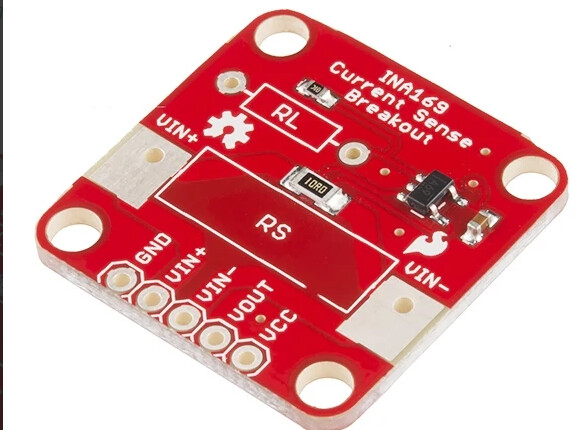
For a solar setup, I plan to read load currents of a 12v lithium Iron Phosphate battery between 0-100 amps with a SparkFun INA169 breakout board. The INA169 is reading from a 100A 75mv shunt (.00075 ohms resistance). The INA169’s load resistor has been removed and replaced with a 100,000 ohm resistor (to be replaced again with a 60,000 ohm, I just didn't have one on hand). As I understand it, the built in 10ohm shunt resistor will have a negligible effect.

The test load is from Peltier cooler and fan on a cheap 30V, 10A adjustable power supply. This power supply has negative, positive, and ground terminals. Load at 12v is about 3.7 to 4 amps.

At first, I tried Reading from an Arduino R4 wifi with an OLED display added, but values were extremely inconsistent, jumping around wildly, even when the multimeter read Vout values as consistent and changing with amperage as expected.

To simplify the setup, I switched to an Uno R3 with only the INA169 attached. Details are below, but a summary in case much of it is unnecessary to the answer: On an R3 with a .104uf capacitor placed before the analog pin, and the arduino powered via my Laptop off of battery power, the INA169 outputs a voltage changing with current as it should, and the Arduino reads it accurately and consistently. Though, based on my calculations, the voltages outputted are higher than they should be. With almost any other power source configuration, including powering the arduino directly from the load’s power supply using a buck converter, either the Arduino doesn’t read correctly or the INA169 doesn’t output voltage.

So I’m pretty sure my issues have to do with finding the proper ground/negative configuration and filtering the signal properly (and/or using better power sources). I’m just not sure of the exact methods and ‘rules’ I’m missing, and I’m also not sure why the output voltage is not at the expected scale. Any insight is greatly appreciated.

Here’s more detailed results with different configurations. I can sketch out the setup if this ends up being hard to follow:

  • With the simplest circuit, only the R3 and the INA169: I got jumping values as with the R4.

  • Adding a .104uf capacitorin parallel right before the Analog input, with the Arduino plugged into my laptop’s USBC port but the laptop not plugged into a power supply: I get consistent readings that match what the multimeter reads and scale with changing amperage as expected (Example: it was about .7v when load is 3.7 amps at 12v). Adding back the OLED screen, results stayed the same. Progress…

  • When I plug my MacBook Pro into its power supply, it still reads consistently, but the readings rise by about 10-20 millivolts. Multimeter at Vout and Arduino readings both show this change.

After adding the capacitor (and later a small resistor in series) and getting these promising results, the following configurations did not work:

  • If powering the R3 via its own AC-DC power supply (reading results via OLED screen), readings jump around again and don’t match Vout voltage via multimeter, which still scales with amperage correctly, but the voltage is lower than before. (Eg: Vout reads: .47v at 3.7A and .38v at 1.9A).

  • Just to see what happened, I connected the Arduino ground to the power supply’s ground terminal (not its negative): Readings occur when the load's power supply is on, and are a consistent value, but don’t scale at all with change in current. Readings don’t scale when reading Vout from the multimeter either.

  • I also tried connecting the Arduino directly to the Load’s power supply negative and positive terminals using its Vin pin and a ground pin and a DC/DC Step-down converter purchased from Adafruit, so all components share the same power source. The Arduino powers up correctly, but the INA169 does not output anything at Vout, even testing with multimeter. This is also true if I connect the VCC of the INA169 to the load’s higher voltage (12v) power supply power directly, keeping its negative/ground on the Arduino’s.

The other issue is even when I get consistent readings matching the actual Vout voltage, the scale of the INA169’s Vout voltage is wrong according to my calculations. The INA169’s Vout scales up and down with changes in current, but the voltage is much higher than predicted based on the resistors I’m using on the INA169. Example: .7v when load is 3.7 amps when calculations say .7v volts should be almost 10 amps.

Here’s the code I’m using, minus any OLED screen code that was included. I had it do bursts of reads:

const int SENSOR_PIN = A0; // Input pin for measuring Vout
// const int RS = 10; // INA169 board's built in Shunt resistance value
const float RS = .00075; // Ohms, 100A 75mv Shunt resistance value
const float RL = 100000; // Ohms, Load resister in INA169 chip
const float R_INA169 = 1000; // Ohms, internal resistance constant for INA169 chip
const float VOLTAGE_REF = 5;  // Reference voltage for analog read
float vout;
float current;

void setup() {
  Serial.begin(9600);
  // Set unused analog pins to pull up to reduce signal noise.
  pinMode(A1, INPUT_PULLUP);
  pinMode(A2, INPUT_PULLUP);
  pinMode(A3, INPUT_PULLUP);
  pinMode(A4, INPUT_PULLUP);
  pinMode(A5, INPUT_PULLUP);
}
void loop() {
  uint16_t sensor_read;
  for (uint8_t t = 0; t < 5; t++). // Burst of reads
  {
    sensor_read = analogRead(SENSOR_PIN);
    vout = (sensor_read * VOLTAGE_REF) / 1023;
    current = (vout * R_INA169) / (RS * RL); 

    Serial.print("Analog Read Value: ");
    Serial.println(sensor_read);
    Serial.print("Voltage at Vout: ");
    Serial.println(vout);
    Serial.print(current, 3);
    Serial.println(" A\n");

    delayMicroseconds(50);
  }
  delay(5000);
}
Please post a hand drawn wiring diagram, with all parts, pins and connections clearly labeled.

Sorry, I only read the frist paragraph, stopped when I read:

The INA169’s load resistor has been removed and replaced with a 100,000 ohm resistor (to be replaced again with a 60,000 ohm, I just didn't have one on hand)

What calculations did you do to get a value of 100kOhms for a current of 100 A?

Does this trace width support 100A?

The shunt resistor you must use is:

Rshunt = V_sense/Imax
= 100mV/100A
= 1mOhm

For 3.3V output then

imagen

RL = Vout/(Is * Rs 1000uA/V)
= 33kOhm


For 5V output then:
RL = 5V / (100A * 1mOhm * 1000 uA/V)
= 50kOhm

However, the maximum voltage output is:

This is due to:

You need at least an input voltage of
Vout = V+ - 0.9V
V+ = Vout + 0.9V
V+ = 5.9V

And finally, if you are connecting that output of the ina269 to an ADC, then you must use voltage follower

I am curious, as someone who built a 7,680Wh battery bank, I used a Victron shunt and associated monitoring meter. Their documentation may be useful.
ICYDK, Victron is considered to be the leader in off-grid power; virtually every boat and most RVs use Victron.

And some photos please.

Sorry, I only got to this again this weekend. I will definitely take some time and absorb this information, thank you. I ordered some OPA340's. When you show that V+ must be at least 5.9V, that just means I can't use it to measure voltages lower than that?

I used a 100k ohm resistor just because it was what I had on-hand, understanding it was too high. I was going to replace it with 60k, giving me 111 amp max read at 5v on my 75mv shunt. The equations I used are in the code provided.

I actually am indeed using Victron charge controllers, and am using VE.direct to read some of the system parameters. I just wanted to do the current measurement myself to learn and save some money.

Here's a hopefully legible drawing of the setup that was most successful, with the Arduino connected to my laptop.

And I also tried to connect the Arduino directly to the PSU with a buck converter. The only difference there is the buck on the PSU's +/- directly and the arduino +/- on the buck's output wires. The Arduino powered up but the INA169 did not output any voltage, as described in the first post.

This setup is currently disassembled, but if I still can’t figure it out once I’ve added the OPA340, I’ll take pictures of the actual setup.

Unless I am not seeing it, the shunt is wired wrong. A shunt goes in the negative side of the battery. one end of the shunt is connected to the most negative battery post and NOTHING else is attached to that. The other end of the shunt connects to ALL the grounds in the system. This is how we know exactly how much charge is in the battery ay any point in time.

+1
That INA chip can only measure high-side (in the + line).
Common-mode of this INA version starts at 2.7volt (2.7-60volt), not at 0volt.
Leo..

Oh jeeze, I literally ordered the INA169 knowing it was high-side but somehow totally overlooked it when I assembled it, and spent hours staring at it when it wasn't working properly and didn't think about that at all... Well, this might be solved...

The INA226 could have been a better choice.
It can measure high (upto 36V) and low-site and has a built-in 16-bit A/D.
Leo..

When you show that V+ must be at least 5.9V, that just means I can't use it to measure voltages lower than that?

No. V+ and Vin+ are different things.

V+ is the power supply voltage, i.e., the signal that provides power to an electronic component (the INA169 in this case).
On the other hand, Vin+ is the input common-mode voltage. These two voltages are independent.

What I said is that if you want a maximum output of 5V on terminal 1 of your INA219, then your power supply voltage (V+) must be at least:
V+ = Vo + 0.9V

or otherwise, If you have a power supply V+ equal to 5V, then the maximum output of the INA169 would be:
Vo = V+ - 0.9v
Vo = 5V - 0.9V = 4.1V
You will get a maximum output voltage of up to 4.1V only. (from 0V to 4.1V)

So since my Vin+, being a 12V battery, is going to be greater than 5.9V in normal conditions (and less than 60V), I can use the battery to supply INA169's V+ as well, instead of powering from the Arduino? While still having them share the same ground. I did do this initially, but it didn't work, I assume because of my low-side mistake and the lack of buffer.

Or, less ideally, account for the 4.1V max in my load resistor choice.

V+ *should * be powered from VCC of the Arduino.
I don't see a great benefit of a buffer, unless Rload has a very high value.
The 100n cap on A0 in your diagram both acts as smoothing and buffering.
Leo..

Yes, you can use your 12V battery to supply your INA219.

Or wait...
What was the goal of your design? What do you plan to measure? I mean, what is your load?

Please remind me the current values you are using for RL and Rs

.

Again, if you want to measure a maximum current of 100A then:
Rs = Vsense/Imax = 100mV/100A = 1mOhm

The maximum power is:
P_Rs = I^2 * Rs = (100^2)(1m) = 10W

You normally buy a 75mV/100A shunt with Kelvin connections for that.
You then calculate for 75mV.
eo..

Thank you for the schematics, it’s helpful! I’m using a .75mv/100A shunt. I’m temporarily using a 100kOh load resistor (within spec at 99.4 kOhm on the multimeter). This will be replaced with a more suitable value in the final iteration.

I'm ultimately going to measure the load on a 12v LiFePo4 battery. The load will be from an inverter powering mostly lights and fans for a terrarium and indoor houseplant setup and will not exceed 1200W, if half that. However, before adding the shunt to the actual system, I'm testing with a variable power supply powering fans and a 12V Peltier cooler.

I don't have the OPA340’s yet, but I did test the INA again, in basically the same way as in my hand drawn diagram, except the shunt on the high side(!), and the Arduino's ground also tied to the Load's power supply negative. The readings were a lot closer, though always lower than the actual load. For example:

With a load of 0.94A at 3V, Arduino reads .26A,
Load of 2.05A at 6V, Arduino reads 1.43A,
Load of 3.8A at 12V, Arduino reads 3A.

The Vout captured by the Arduino was consistent with my multimeter's reading at Vout.

Unfortunately I didn't have anything around to increase the load at 12V and see if the discrepancy changed with higher amps. Maybe I'll put together a few more peltier and heat sinks, or just install the shunt for real and test from there. If the difference stays below 1A at higher amps too, that is usable for me, though it’d be great to be more accurate.

Unless there’s more to fix/improve, I’m guessing the next step is to just wait for the OPA340's to arrive.

Both the INA169 and the ADC have gain and offset errors. Unless you calibrate out those errorrs your measurements will always be wrong.
Using a 100K resistor will give the poorest resolution and accuracy.

Well I'm at least glad to hear I'm on the right track. I'll look into calibration, thanks.