volatile int16_t pwm = 0; //pwm value
volatile int16_t trig = 0; //timer value
#define pin 8 //pin the interrupt is attached to

void intHandler() //function to call on interrupt
{
    if(digitalRead(pin)) //if the pin is HIGH, note the time
  {
    trig = micros();
  }
  else
  {
    pwm = micros()-trig; //if it is low, end the time
  }
}

void setup(){
  pinMode(pin, INPUT); //set the pin to input
  attachInterrupt(pin,intHandler,CHANGE); //attach the interrupt function "intHandler" to "pin" whenever the state changes
  Serial.begin(9600); //begin serial comms
}

void loop()
{

  Serial.print("PWM = ");
  Serial.println(pwm);
}
What could I do to narrow down what the problem is. My guess is that it is a hardware issue but I'm not sure.
Riva:
Can you tell us what hardware your using and how it's wired up.
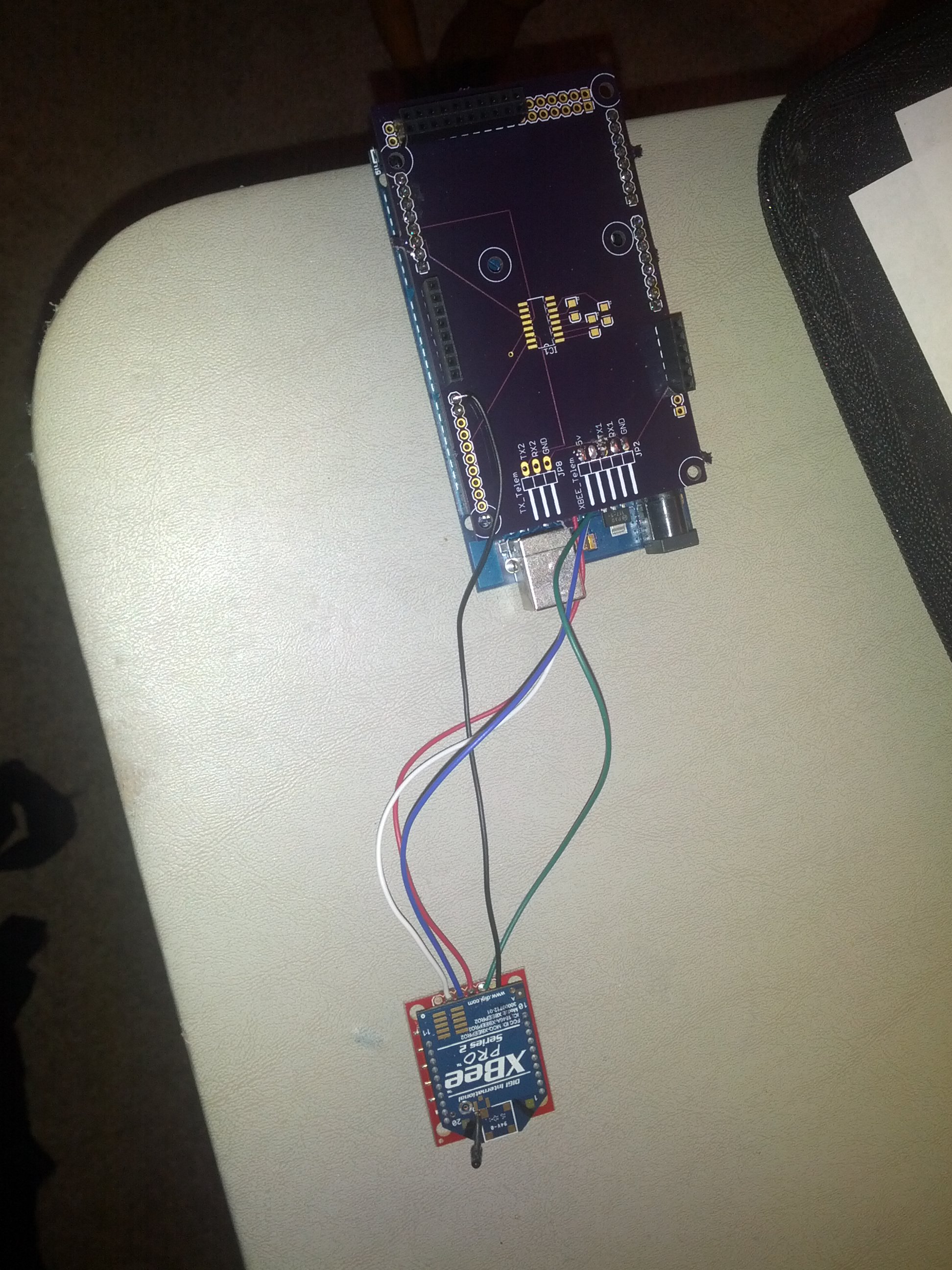
Of course, sorry for not including that in the OP. My XBee is connected via this: SparkFun XBee Explorer Regulated - WRL-11373 - SparkFun Electronics the RSSI output (pin 6) is connected to pin 8 on my mega. The serial is connected via serial1 and obviously ground and 5v are connected as well.
A quick look and it seems the RSSI value is a PWM signal out of pin 6 of the XBEE and it should be read using something like...
rssiDur = pulseIn(digitalPin, LOW, 200);
Your original sketch was very close but the pulse width your measuring should be the LOW pulse and not the HIGH. Adding the 200 timeout to the pulseIn command means it will not wait forever if no pulse (no signal) arrives within time.
You don't do anything with 'duration' in your sketch but I assume that because it was just a demo.
Hope this works and helps.
Riva:
A quick look and it seems the RSSI value is a PWM signal out of pin 6 of the XBEE and it should be read using something like...
rssiDur = pulseIn(digitalPin, LOW, 200);
Your original sketch was very close but the pulse width your measuring should be the LOW pulse and not the HIGH. Adding the 200 timeout to the pulseIn command means it will not wait forever if no pulse (no signal) arrives within time.
You don't do anything with 'duration' in your sketch but I assume that because it was just a demo.
Hope this works and helps.
Thanks for the input. I tried your suggestion along with both 200 and 500 for timeout and both LOW and HIGH, rssiDur is still returning 0.
PaulS:
Just the standard one. What are you intending to use the RSSI value for? Determining distance between two objects is not something RSSI is useful for.
I'm sorry, but this really doesn't answer the question. Do you intend to transmit data only if RSSI is above some value? How will that be better than just transmitting data that doesn't get received by another device, because the signal strength is too low?
Once I'm able to get anything other than zero from the input, the number will be displayed on a tft as a bar graph. This will give me the ability to determine if I can reliably send a command to the quad rotor to do a task.
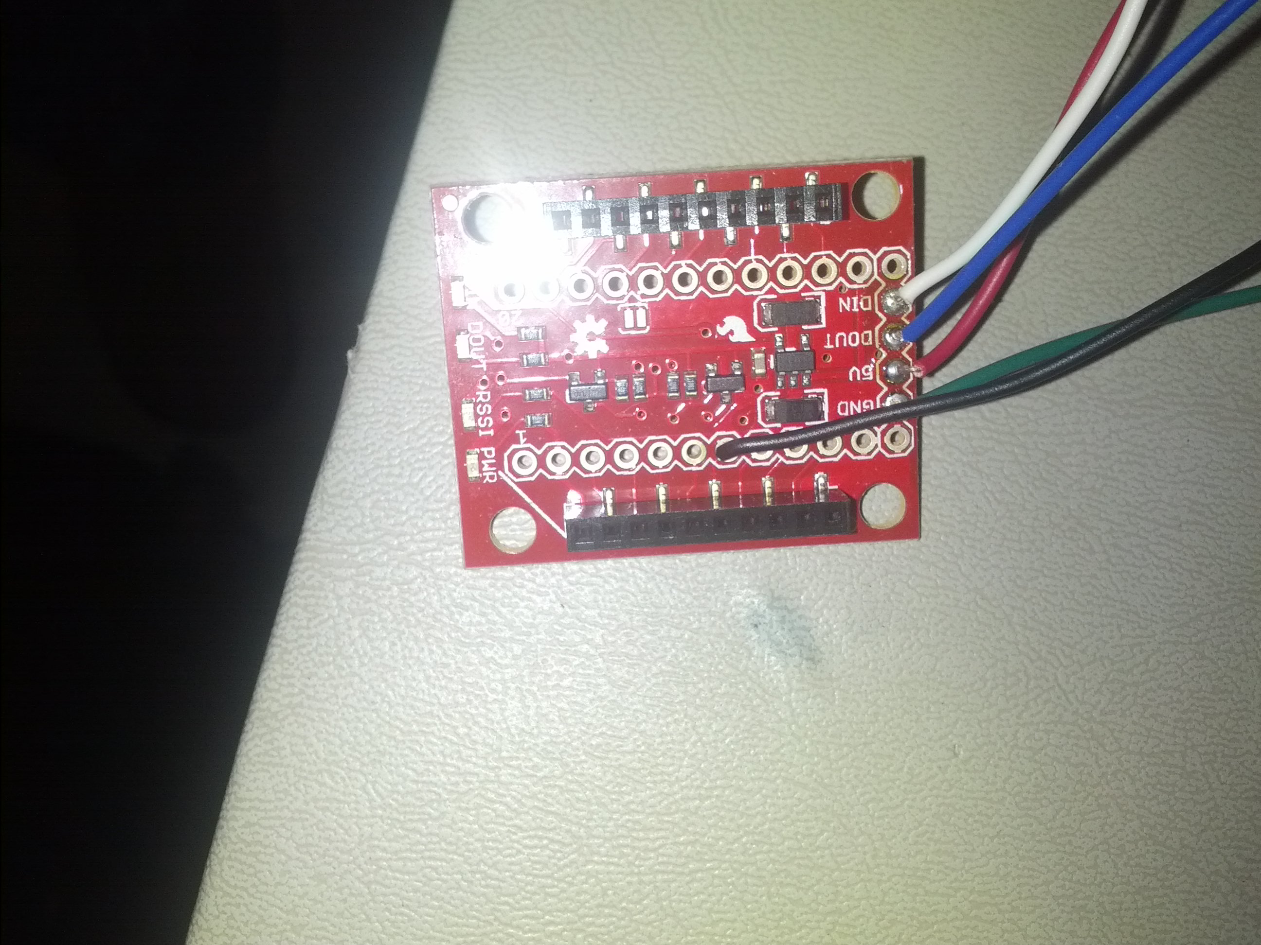
Can you post more details of what Arduino your connected to and how the XBee breakout is wired up. Does serial work okay or is nothing working?
EDIT: Sorry, reading back I see you had mentioned Mega. I think a good image/schematic of how it's all connected is really needed. If you take pictures then do ones with and without the XBee mounted.
the RSSI output (pin 6) is connected to pin 8 on my mega.
Is this pin 6 of the XBee or pin 6 of the Sparkfun breakout board?
I actually have the xbee attached to a shield I've been working on. The serial is connected to serial1 on the mega and has been working flawlessly. Currently the RSSI wire is connected from pin 6 on the XBEE directly to the pin 8 header on the shield connected to the mega. If more pictures are needed please let me know.
Looking at the pictures and your schematic and the principle looks good though we cannot be sure of the wires soldered to JP2 but if the XBee is working and RX/TX are giving valid data then I can only assume it's good.
Have you tried connecting direct to the Mega without your shield or at least tried a different pin for the RSSI just in case the shield is not passing pin 8 through as expected.
Does the RSSI LED on the Sparkfun breakout board adjust in intensity depending on signal strength?
Riva:
Have you tried connecting direct to the Mega without your shield or at least tried a different pin for the RSSI just in case the shield is not passing pin 8 through as expected.
Does the RSSI LED on the Sparkfun breakout board adjust in intensity depending on signal strength?
Yes I have connected directly to the mega on several different pins and with the same results. I've also tried running through a spark fun logic level converter too, thinking that maybe 3v wasn't enough to identify the edge of the pulse. Check XBee RSSI out to Arduino Mega - General Electronics - Arduino Forum for the findings of that question. Glad to know that my antics aren't just crazy ideas, that I am working good troubleshooting practices. Ive also checked continuity from the pin on the header of XBEE socket to the wire leaving the adapter, that's good too. The glowing led would lead me to believe that the RSSI is working on the XBEE adapter. The one thing that I hadn't checked is the dimness of the RSSI LED. Inside how far apart do they need to be for me to notice a change?
Thanks for all of the help in troubleshooting this!
Loren:
The glowing led would lead me to believe that the RSSI is working on the XBEE adapter. The one thing that I hadn't checked is the dimness of the RSSI LED. Inside how far apart do they need to be for me to notice a change?
I'm not sure how far apart you would need to be but maybe turning off/on the other device your connecting to would cause the RSSI LED to go on/off so you at least know the pin is defined as RSSI and not PWM.
I'm running out of ideas here apart from the pin being configured for something other than RSSI or the voltage level is not high enough to register on a 5V arduino.