First time trying to write my own program for Arduino.
I have an Arduino Uno.
I have a 12v power relay.
I have a generic multi-coin acceptor.
I have this fortune teller machine. when you press a button, it tells a fortune.
I've taken the button apart so that its two wires. if those two wires touch, it essentially "presses" the button and the fortune teller does its thing.
i'm trying to make it, so that if i put a coin in the coin acceptor (already programmed the acceptor to take quarters, it sends a pulse when the coin goes through) then it does something so that the two wires "touch" and then the fortune teller goes off.
so to simplify, if pulse is detected, then connect two pins. but i couldnt seem to get that to work.
so then i tried the power relay, power the relay if pulse is accepted and i had the button wires in the NO part and the CON part.
im a total noob. ive tried many variations of things so far but no luck. where am i going wrong?
void setup() {
   // Set pin 2 as input and pins 5 and 8 as output
pinMode(2, INPUT);
pinMode(5, OUTPUT);
pinMode(8, OUTPUT);
}

void loop() {


// Check if pulse is detected in pin 2
if(digitalRead(2) == HIGH) {
  // Connect pins 5 and 8
  digitalWrite(5, HIGH);
  digitalWrite(8, HIGH);
}

}
What is sending the pulse? What voltage?
Do you have the ground of that connected to the ground of the Arduino?
The relay coil should have one connection to ground and the other to an output pin of the Arduino, not two pins.
Show a diagram of your wiring.
// Include the necessary libraries
#include <Arduino.h>

// Define the pins
#define PULSE_PIN 2
#define RELAY_PIN 6

// Define the variables
int pulseState = 0;

// Setup function
void setup() {
  // Set the pin modes
  pinMode(PULSE_PIN, INPUT);
  pinMode(RELAY_PIN, OUTPUT);
}

// Loop function
void loop() {
  // Read the pulse pin
  pulseState = digitalRead(PULSE_PIN);

  // If pulse is detected, turn off and on the relay
  if (pulseState == HIGH) {
    digitalWrite(RELAY_PIN, LOW); // Turn off the relay
    delay(1000); // Wait for 1 second
    digitalWrite(RELAY_PIN, HIGH); // Turn on the relay
  }
}
this is more or less the code i was using when i was trying the relay
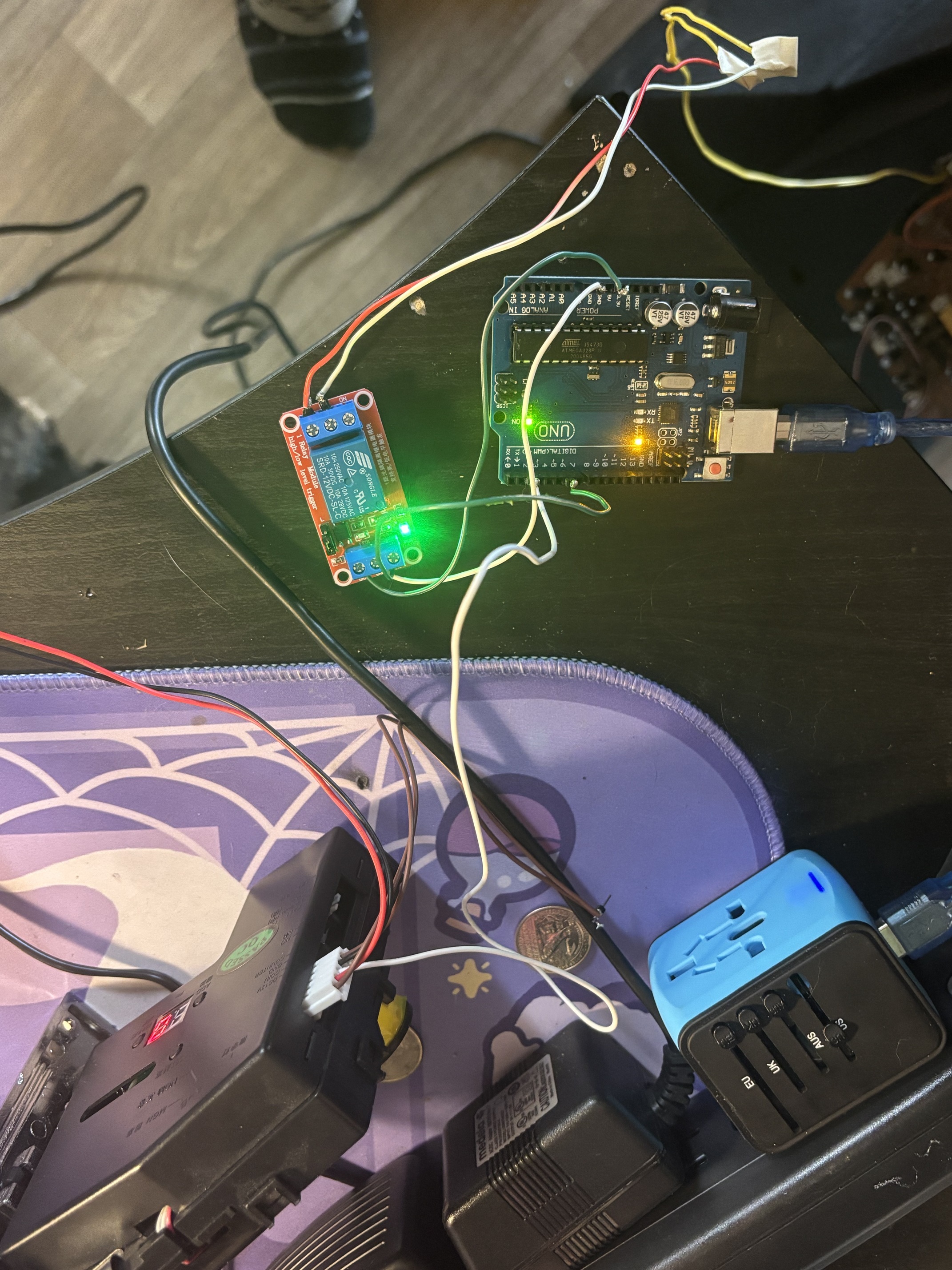
Hopefully this isn’t too confusing a mess to understand. External power to the coin acceptor. USB to power arduino. Arduino powers the relay. Relay connected to pin 6.
Coin acceptor connected to pin 2 using the “coin” wire that comes off the mechanism. The user guide said that’s what sends the pulse.
Coin mechanism programmed to send 1 pulse per quarter.
From what I can tell, the relay side is fine, except your odd choice of the normally closed contacts.
Normally, the two wires aren't touching, so it seems more like you should mimic that, and have the two fortune teller wires normally not connected by the relay. NO. Normally open.
And as @LarryD days, you need twelve volts 12 to run the relay; even if you find a five volt 5 equivalent, you should not take power for it from the Arduino board.
The logic signal that runs the relay is fine coming from an output pin, and writing it HIGH and delaying a bit then writing LOW should work.
Or maybe LOW, then HIGH, depends on the relay module, some can be configured to work one way or the other. But that's just an experiment or two once the relay is properly powered.
Get that half working with a pushbutton on the input where you wanna have the coin detector pulse. Use INPUT_PULLUP mode, and make the relay do its thing when your pushbutton, wired between the input pin and ground, reads LOW (pressed!) on the that pin.
Then the coin detector can be considered, it will just fill in for the pushbutton.
But get the simpler pushbutton makes a fortune part work first.
OK, so the easiest solution to my problem was to get a lever micro switch. I installed it so that the quarter falls and immediatley hits the micro switch. I soldered one half of the fortune teller button to NO and the other to CON. so when the quarter drops it just for a quick sec connects the two halfs of the button starting the machine. No arduino necessary. While i would have liked to figure out how to make it work with arduino, this was the fastest option for me to move on with the project. thank you to everyone for their assistance.