Hello everyone, I am still new to coding ESP32 so please be kind on my mistakes. I am trying to calculate the angle of arrival of a sonar signal using the time difference of when two receivers receive the signal. Below is a diagram and a picture of my set up. The distance between A and B is 13cm. A is connected to pin 4, B is connected to pin 5. I am using the raw signal from the OPAMP of the HCSR04 into a comparator (which also converts it into 3.3v) into the ESP32
Now here is the problem. At 13 centimeters, the maximum time difference i should get is 379us. But when the transmitter is parallel to the receivers, i get anywhere from 420-600us. And when i hold it and the middle of the receivers, the time difference is ±1us which is expected. This leads me to believe the circuitry is good but my code is faulty. Here is the code in question.
volatile unsigned long timestamp1 = 0;  // Timestamp for pin 4
volatile unsigned long timestamp2 = 0;  // Timestamp for pin 5
volatile unsigned long lastInterruptTime1 = 0;  // Last interrupt time for pin 4
volatile unsigned long lastInterruptTime2 = 0;  // Last interrupt time for pin 5
int ignoreTime = 10000;  // how long to ingnore subsequent pings in microseconds
volatile bool flag1 = false;  // Flag for pin 4
volatile bool flag2 = false;  // Flag for pin 5

// ISR for pin 4
void IRAM_ATTR reciever1() {
    unsigned long currentTime = esp_timer_get_time();
    if (currentTime - lastInterruptTime1 >= ignoreTime) {
        timestamp1 = currentTime;
        flag1 = true;
        lastInterruptTime1 = currentTime;
    }
}

// ISR for pin 5
void IRAM_ATTR reciever2() {
    unsigned long currentTime = esp_timer_get_time();
    if (currentTime - lastInterruptTime2 >= ignoreTime) {
        timestamp2 = currentTime;
        flag2 = true;
        lastInterruptTime2 = currentTime;
    }
}

void setup() {
    Serial.begin(115200);  // Start serial communication
    pinMode(4, INPUT_PULLUP);  // Set pin 4 as input with internal pull-up resistor
    pinMode(5, INPUT_PULLUP);  // Set pin 5 as input with internal pull-up resistor
    attachInterrupt(digitalPinToInterrupt(4), reciever1, RISING);  // Attach interrupt on pin 4
    attachInterrupt(digitalPinToInterrupt(5), reciever2, RISING);  // Attach interrupt on pin 5
}

void loop() {
    if (flag1 && flag2) {  // If both interrupts have triggered
        long timeDifference = timestamp2 - timestamp1;
        float timeDiffSec = timeDifference / 1e6;  // Convert to seconds
        float ratio = (343 * timeDiffSec) / 0.13;
        ratio = constrain(ratio, -1.0, 1.0);  // Ensure it stays between -1 and 1
        float angleArrival = asin(ratio) * (180.0 / PI);  // Convert to degrees

        Serial.print("Time difference: ");
        Serial.print(timeDifference);
        Serial.print(" us  Angle: ");
        Serial.print(angleArrival);
        Serial.println("°");

        flag1 = false;
        flag2 = false;
    }
}
If anyone has any advice on this, please share. I dont know what im doing wrong.
micros() is faster than calling esp_timer_get_time (32 bits instead of 64 bits) and would not matter much since you only handle a difference.
Also t2 - t1 suggests that t2 is always larger than t1 which might not be the case depending which sensor got the signal first and in that case you'll get a huge number from the subtraction . You might need to take that into account
Indeed, the t2-t1 thing did cause large negative numbers often but i figured ill fix this problem first. so thanks for that. But the problem still remains. This is the code i used
If you are attempting to convert the 5V pulse from the sensor to 3.3V, I do not think it will work. The op-amp is powered with 5V and will output 5V and could damage the ESP. The pull-up resistor won't fix that. Anyway, no op-amp is necessary to convert to a 3.3V signal. Just a voltage divider.
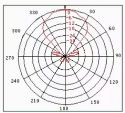
As pointed out above, the sensors have narrow 30° beams, so anything more than 15° away from the centre line is unlikely to be reliably detected. Is it possible what is being picked up is an echo from some other object which is further away? That could explain why the difference is more than expected.
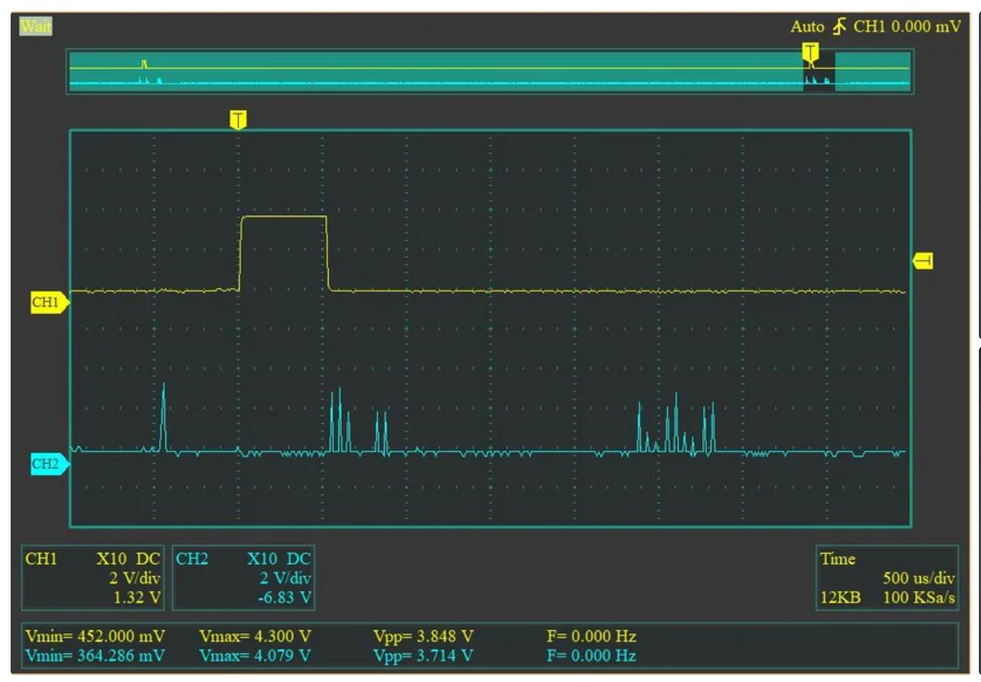
The pulse you are talking about here is the yellow trace. The reason i cant use the echo signal from the sensor is because it only sends out one after the sensor has fired. That means a signal is out in the air, that will interfere. Thus i solder a wire directly to the sensors opamp. And that means i deal with the bottom trace now
The opamp signal goes into a comparator to digitize and also set the voltage level to 3.3v (see the pullup resistor.
On the Atmega328P, you would use the input capture register to capture the current timer count when a certain pin changes state. That state change could also trigger an interrupt which would save that value so the next transition could then be captured. But you might need some logic chips to use the same pin for two sources.
Does the ESP32 have such a function? Google says:
Yes, the ESP32 does have an input capture register functionality, which is accessible through the "MCPWM" peripheral, allowing it to detect edge transitions on a signal and measure the time between them, effectively acting like an input capture mechanism.
As far as i understand from reading the datasheet for this transducer (TCT-40 T/R). This only counts for the transmitter. So I would need to ensure both the receivers fall under the 30 degree cone? Ill test this in a bit and will let you all know
The echo pin cannot be used for passive listening like i am here. It is meant to give out a signal proportional to how long the transmitted signal took to came back.
For my 'passive listening' i am instead using the 'raw signal' directly from the last stage of the TL074 chip on the sensor
Have you checked with your scope to see if the time difference between those two signals at the two digital inputs to the ESP32 corresponds to the values your code is producing? I'm just thinking that would indentify whether there's something wrong with your code, or something wrong (or at least unexpected) with your hardware.
Ok, I understand a little better now. The third sensor (not labelled, let's call it "C") is sending out the pulse, and sensors A and B detect it. Sensor C isn't used to receive anything. Sensors A and B don't get triggered by the Arduino, so don't send any pulses, but they receive the pulses from C.
This part I still don't get. I don't think it will do that. Does the op-amp used have an "open-collector" output?
Another thing that struck me. How are you allocating the 2x ISRs to the ESP32's 2 CPU cores? If they both run in the same core, they can't execute simultaneously as they would need to when the signal is directly ahead.
That hadnt struck me actually. This explains why i could never get the difference to come out at 0, always plus-minus 1. This seems to be the reason why. Id like to use the other core for wifi and whatnot still so i think i can live with that 1 microsecond.
micros() on esp32 calls esp_timer_get_time()...
You could try esp_cpu_get_cycle_count() for even higher resolution (don't forget to convert back to microseconds)