Trying to run Arduino on an ATmega32M1. Compiles, uploads, but doesn't run.

Westfw, I've tried setting both pins PD1 and PB1 HIGH. I use PD1 because my built in LED on my custom board for the ATmega32M1 is attached to that pin. I've tried PB1 because that is the pin used in Coding Badly's code and I prefer to use other people's code as is without introducing any of my code first so that my simple brain doesn't mess up what they've already done!

So my test process is:
I will copy someone else's code (like Coding Badly's) and use it as is and test the physical PB1 pin (because that is the one in his code) with an LED & test lead (as shown in the picture). I then test all the other physical pins with the LED & test lead while still running the same code. Then I change the code so that it points to pin PD1, and check to see if the built in LED "blinks." If still unsuccessful, then I test all the other pins with the LED & test lead while still running the same code. I repeat the same process with the bare chip as shown in the attached pictures.

Yes, I do have the ATmega32M1 (three of them!). Yes it's naming convention is confusing!! It is not pin compatible with a chip like the ATmega32U4 either! It has been a bit frustrating searching the internet for info and other people's work concerning the ATmega32M1 because all the other "ATmega32..." chips come up as hits too (like that ATmega328, ATmega328p, etc.).

Attached is a picture of my test setup with the RedBoard as the ISP, LED & test lead, and the ATmega32M1 bare chip.

Attached is a close up picture of the ATmega32M1 bare chip attached to the RedBoard ISP.

Attached is a close up of the custom board I made for testing the ATmega32M1.

I would also like to mention that I have gotten the ATmega32M1 to respond at one point--sort of. Back when I first had just the code for adding the ATmega32M1 to the avrdude.conf and the board.txt files, I was able to compile, upload, and run the standard "Blink" sketch. It wasn't driving the right pin, but using my LED & test lead, I was able to figure out which pins it was driving. It was weird though.

If I set the code in the standard "Blink" sketch to:

int led = 13;

then it would drive physical pin PB5.

If I set the code to drive pins 0, 1, 2, 3, 4, 5, 6, 7, 16 or 17 then it would drive physical pin PD0.

If I set the code to drive pins 12, 14, or 15 then it would drive physical pin PB4.

If I set the code to drive pins 8, 9, 10, or 11 then it would drive physical pin PB0.

At that time, I was happy to at having code compile and upload without errors and I was at least blinking something, even though it was the wrong pins and in such a weird way. I assumed that the weird behavior was because a specific "pins_arduino.h" had not been written for the ATmega32M1. So I set about to write my own "pins_arduino.h" for the ATmega32M1. Since then I haven't been able to "blink" any of the pins. I've tried to go back and recreate the first situations again, but to no avail. I've tried with a clean install of Arduino 1.0.5 and the standard "pins_arduino.h" and still to no avail.

Do you have a pull-up resistor attached to the RESET pin?

Coding Badly, I do have a 10K pull-up resistor on the Reset pin of the custom board and I've added one to the bare chip setup.

Use avrdude to read the current fuse bit settings. Post the settings. If you need help, say so.

Coding Badly, I forgot about being able to read the fuses via avrdude. Thanks. Here is what I got off the chip:

lfuse: 0x62
hfuse: 0xdf
efuse: 0xff
lock: 0x3f

Now I'm going to look up what that means!

This is what I use...
http://www.engbedded.com/fusecalc/

The processor is configured to run at 1 MHz. Ensure f_cpu is...

atmega32m1.build.f_cpu=1000000L

...and retry one of the simple programs from above.

According to the datasheet (http://www.mouser.com/ds/2/36/doc8209-242488.pdf) and with the help of the fuse calculator here: AVR® Fuse Calculator – The Engbedded Blog.

Low Fuse--62:
CKDIV8 is set = microprocessor is running at 1/8th of clock--1MHz
CKSEL3..0 is 0010 = the internal 8MHz resonator
SUT1..0 is 10 = 20clock cycle +65ms startup time

High Fuse--D9:
RSTDISBL is not set = RESET pin is to be used as a RESET pin!
DWEN is not set = the RESET pin is not used for debugging
SPIEN is set = Serial programming and Data downloading is enabled
WDTON is not set = Watchdog time is not always on
EESAVE is not set = EEPROM memory is not preserved through chip erase
BOOTSZ1..0 is 11 = Boot size is 256 words, 4 pages
BOOTRST is not set = Upon reset the application is started

Extended Fuse--FF:
PSCRB is not set = All PSCOUT pins are normal ports upon reset
PSCRVA is not set = not applicable with PSCRB not set
PSCRVB is not set = not applicable with PSCRB not set
BODLEVEL0..2 is 111 = Brown Out Detection Level is disabled

engbedded's calculator is stating that the default settings for the ATmega32M1 is:
Low Fuse--0x41, High Fuse--0xD9 & Extended Fuse--0xF9

According to pages 276 & 277 of the datasheet though, this seems to be in error. The default seems to be:
Low Fuse--0x62, High Fuse--0xD9 & Extended Fuse--0xFF

It looks like the present fuse settings on my chips only deviate from the default settings in the High Fuse where it comes to the Boot Size (BOOTSZ1..0). My chips are at 11 so the smallest boot size of 256 words whereas the default is a setting of 00 so the largest boot size of 2048 words. Since I'm not using a bootloader would this matter? Either way the Application Flash section starts at memory address 0x0000 (page 270) and since the BOOTRST bit is not set in the High Fuse, the application should be started upon reset.

What do you think? Would it hurt to go back to default settings (according to the datasheet, not engbedded's suggested setting)? Do you see anything in the fuse settings that would keep the uploaded application from loading?

Coding Badly, I too like engbedded's calculator. Even though it seems like the suggested default fuse settings for the ATmega32M1 is wrong on that site, I like how easy it is to visualize and manipulate the fuse settings there.

I have set the board.txt's setting for the microprocessor's speed to 1MHz (1000000L). In my original post I do show a setting of 8MHz, but that was because I had changed it just in case something in the fuses had been changed and the microprocessor was looking for a different speed. With you reminding me concerning reading the fuses via avrdude, I was able to confirm that the chip is still expecting 1MHz. Thank you.

Since I'm not using a bootloader would this matter?

No.

What do you think? Would it hurt to go back to default settings (according to the datasheet, not engbedded's suggested setting)?

It would not hurt but it would not help.

Do you see anything in the fuse settings that would keep the uploaded application from loading?

No.

RaMansell:
Even though it seems like the suggested default fuse settings for the ATmega32M1 is wrong on that site

The settings are based on an XML file produced by Atmel. Occasionally there are mistakes in the file. Occasionally the site is out-of-date relative to the file.

If you do believe there is a problem I encourage you to contact Atmel and ask for a correction. (I don't know how to do that.)

I also am developing a project using ATmega32M1 with CAN bus. I'm considering making a full Arduino format board (I guess open source and the works). I see the pin mapping problem is quite a challenge.

RaMansell, when bringing up a new board, these new processors are much more forgiving than in the older days. (I suspect I was bringing up microprocessor boards before many visitors here were even born.) Quite a number of I/O and other important pins had to be working correctly for a micro-controller to boot properly.

In these new class processors with internal clocks, it is possible to start a level of debugging with only the reset and program loading pins working. But an oscilloscope is essential -- when you mention I/O happening or not, I don't see if you were using an oscilloscope, hopefully you can get access and knowledge of how to use. Be sure that the reset pins is toggled according to data sheet when programming occurs. And I would use any way possible to identify that any portion of the loaded code is executing--preferably from the very first before the C language startup even executes. I'm not sufficiently familiar with the Arduino compiling environment, but there are definitely start up routines that execute long before the C mainline, and that mainline is going to have to be running to get to the Setup and Loop routines for your Arduino sketch code to ever execute.

In that regard, some seemingly off topic questions:

Is this a commercial project, or is the code you are to write going to be released as open source?

The reason I ask is that you can't release any product based upon the Arduino libraries without making that project open source -- that is the license you agree to to use the Arduino code and libraries. (You signify agreement by using, if you disagree than according to license you are simply commanded to not use. So you are not forced to agree, just forced to not use the library.) If you intend a non-open source release of the system, you might as well start getting used to another development environment.

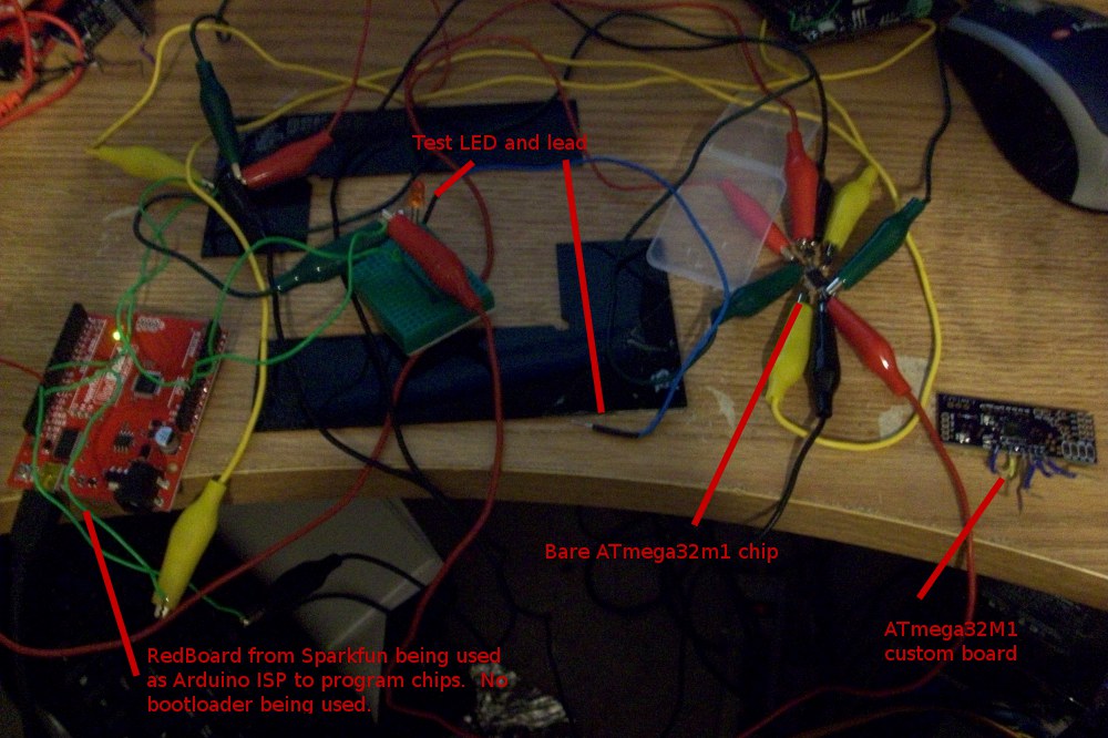
That said, I'm looking to see how you programmed the chip. (I see, using a UNO as ISP.) If you have wired the standard 2 X 3 programming/debugging header on your new board, and can check that pins are properly connected according to the ATmega32M1 data sheet (not as per other Arduinos, but as per standard debugger/programmer for that particular chip), then another option presents. You can obtain one of the new Atmel ICE debugger/programmers for $55 or so. (I'm sure others here can recommend other similar tools, this is the one we have in our shop.) Then downloading the Atmel Studio you can program a minimal application for the chip and check that your board is working. Use the libraries there (yes difficult to understand, but there are examples) you can single step your way through code using the debugger. In this way you assure that the chip is actually working. Issues of the programming and reset pins, bypass capacitors, proper power supply voltages can prevent proper operation. (By the way if you obtained an Atmel ICE and tried it on a UNO, expect to replace the bootloader as that will erase it!) While I don't at the moment remember how to do it, I'm pretty sure you can even break into the code you loaded (or thought you loaded) as it runs, and inspect step by step in assembly language. There are even some "Arduino" related software tools in Atmel Studio, though I think there may be some costs associated with parts of that, the rest is free.

If you're intending commercial release, you are going to have to recode in some library like that provided by Atmel Studio anyway, so the experience is not wasted. We have found it useful to use Arduino's for early testing, before recoding to target systems "the hard way," so we can quickly knock out prototypes and test system ideas -- this approach of starting with Ardino environment is not in any way to be discouraged.

Next I'm not entirely familiar with the Arduino's start up environment before calling C mainline. Does it attempt to run on the external crystal/resonator? If so, then your modified environment may still be loading code to set that change up, but using the code for the other variants of the ATmega. So one must do couple of things--be sure it properly codes for the M1's crystal, and as you have not done insert the crystal (and properly sized capacitors) or resonator. So how is you say you are not using the external resonator? You know the startup code does not switch to that or you have debugged through that? I suggest making sure what is happening at the very first instructions executed after reset, and code your own experiments there if not getting to the C mainline. (Yes you might have to learn assembly language.) These are standard activities when bringing up a new board design, especially if not using code already tested on that particular micro-controller, which is why I suggested at lest testing with startup code pretty much known to work on the M1. (By the way, don't just trust Atmel, the Atmel Studio is targeted to a huge number of targets and I've had to send error reports on many issues.)

By testing with a single stepping debugger (quite affordable now) you verify that the chip is actually executing and can find out exactly what instruction causes it to suddenly stop working. And if you can break into the code from the Arduino environment, you can find out exactly what the instructions are doing--how they might be mapping the pins incorrectly for example. (Yes the direct port banging is proper way to avoid those issues at first.) Unfortunately this all takes a considerable amount of time, purchasing and loading new tools, getting familiar. If you are developing a "product" this all generally becomes part of the process for initial debugging.

I am not sure the licensing terms of the Arduino IDE and libs are so closed, per the FAQ: http://arduino.cc/en/Main/FAQ one may use the libs w/o disclosing source - providing object files are made available for future re-linking:

" Using the Arduino core and libraries for the firmware of a commercial product does not require you to release the source code for the firmware. The LGPL does, however, require you to make available object files that allow for the relinking of the firmware against updated versions of the Arduino core and libraries. Any modifications to the core and libraries must be released under the LGPL. "

Seems a bit odd to me, as I know at times changes in the libs have caused me issues when some detail of the functions are 'revised'. So not sure how useful object files really are :cold_sweat:

RaMansell: Please keep us updated on the progress you are making. I am looking to migrate a couple of my projects to CAN, and am looking at the ATmegaxxM1 lines. Just put in an order for a few sample CPUs and will be able to role up my sleeves in a week or so - so please keep posting the progress and changes you have made.

Thanks
-al-

Wanting to pick this thread back up as I am ready to see about getting a ATmegaxxM1 uC to work within the Arduino IDE for a solar MPPT controller I am working on: http://smartmppt.blogspot.com/.

Along with the work noted here, I found this effort where he focused on the boot-loader and the Serial port:

http://spaces.atmel.com/gf/project/arduinoallegro/

https://github.com/codinghead/Arduino/compare/allegro

Between the two it is apparent that a big chunk of development has been tackled, with a bit more around the PWM / timers / interrupts I am sure.

But here is my question: What is the best way to handle the large number of the Arduino IDE libraries being touched? Does one include the modified routines somewhere in the sketch folder, or does one need to make a 'custom' IDE environment? Is there a process for submitting additional CPU support into the official Arduino source tree (ala like the Tiny lines have been)?

Am asking as I like to do my projects using the Arduino IDE, makes it easier for others to modify, and I have no problem distributing custom boards.h nor even bootloaders. But if I end up needing to distribute (and maintain) more significant portions of the IDE, perhaps I should just go with an AVR tool.

So, looking for some advise - how best to proceed with the 'logistics' of this effort if you will. What to change I can figure out, no doubt asking questions along the way. But what to do after that I could use some hints on :smiley: