I made a working prototype with a homemade optoisolator device (Led glued to a photoresistor and covered in blue tac). I power the led with my arduino, and solder the legs of the photoresistor to either side of a button on an external device (works fine so far on my xbox controller to replicate button presses, and also on my pc power switch to turn pc on/off).
I'm guessing this works because the resistance of the photoresistor when in darkness (about 1 million ohms) is greater than the pull down/up resistor on the external button, so nothing happens. and when the photoresistor is under led light the resistance of the photoresistor falls to near 0 ohms, mimicking a button press. ??
I want to make a larger array of optoisolators, but in a smaller space. e.g 16 channels on a small device i can attach to the back of my xbox controller. and each channel is connected to either side of a single controller button. the biggest arrays i've found online are 4 channel smd components, so i'd need 4 of them.
Price wise i don't want to spend too much, but all i could find are AC optocouplers, these on ebay. i also found the datasheet.
It says they are for AC devices, but would they still work using an arduino pin to turn on/off the led (through a 330 ohm resistor)?
Would they work the same as my blue tac and glue photoresistor? It says it uses phototransistors, so would i need to connect the emiter to the ground side of the external button, or would it work either way? i don't want to damage my xbox controller finding out which side is ground (i don't know what i'm doing), plus they may be using pull up resistors, hmm.
Also the data sheet says the collector - emitter has a minimum breakdown voltage of 80V , is that the maximum it can take? or the minimum required for it to become saturated? , but alot of these optocouplers say the same kind of thing. i tihnk the xbox runs on 3v3 or maybe even 1v8?
i feel alot more comfortable using optoisolators, but can't find cheap 4 channel smd components. anyone know of any?
edit: plus all the optoisolators use transistor outputs. Is my led glued to photoresistor not a optoisolator? what did i make? isi t manufatured in multi channel in SMD form??
this is what i made. It's an led powered by the arduino , and it's glued to a light dependent resistor (and covered in blue tac to keep the light out), which is soldered to the button of an external device. When i turn the led on, it "presses" the button, so in this example it switched on/off my computer
These are examples of the smallest optocouplers I know.
They have 4 independent optocouplers, and can be found in the SMD-16 package.
ILQ615-2X007
ILQ615-1X009
ILQ74-X009T
I'm just thinking about space, but if they're the same size then DIP will work too. I don't want to spend more than £3 per 4 channel array. i'll need 4 of them.
But now i'm confused about what i need, when i search for opto-isolators they use photo transistors. Mine was just a photo resistor. I'm worried about ruining an external circuit if i use a photo transistor, do you have to be careful with polarity? I don't know if the external circuit button has a pull up or pull down, doesn't matter with photo resistors, they seem safer?
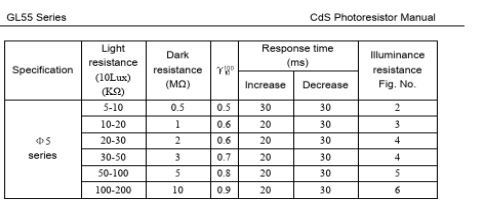
I must have ones slightly different, i measured them in full light at 70 ohms, and 8 million ohms when covered in blue tac.
i want to control more buttons, about 16 or so
Maybe i don't need optocouplers, they use photo transistors? is there a chip that uses photo resistors like mine? is that a thing? if so what is it called? i've been calling it an optoisolator, but i think i'm wrong.
Why aren't phototransistors suitable for you? Optocouplers are a standard way to manage external control to device buttons without interfering with its circuit.
"Photoresistor -based opto-isolators" (just found the term on google) seem the safer option for me, but i can't find any small arrays for them, i guess they're old tech/ not made/ anymore, seem to only be used in guitar amplifiers etc.
i'm worried if i use optocouplers then i'll get the polarity wrong, so emitter goes to the ground side of the external button? How do i make sure what is the ground side? What is DMM?