Thanks for the help sir @ShermanP . I have several questions tho, is the VBAT the coin cell on the ds3231 and why is it tied to the BAT (or is it the same as the BAT)? The EN pin on the boost now is floating because of PNP transistor, am I wrong? Shouldn't it be pulled-low/pulled-high (as per the datasheet of that module)? Lastly, is the VCC on the DS3231 powered by the GPIO out on the ESP32?
No, Vbat is just the main battery. It connects to the power input of the boost converter. I just assigned that name becasue I had drawn the converter in the middle of the other parts, and didn't want to snake a line to it in the drawing.
The EN pin does need a pulldown resistor. I showed in in a previous drawing, but forgot it on this one.
I showed the DS3231 powered by a GPIO port on the ESP32 so you could switch the DS3231 into coin-cell backup mode if you want. It will use less power that way. But it may be easier to tie its Vcc to the ESP32's 3.3V pin so it will get power whenever the ESP32 is on. You need Vcc to be 3.3V when you are communicating with the RTC over I2C because it powers the pullup resistors on SDA and SCL, assuming you have those on the module. But otherwise the RTC will run just fine on its coin cell at about 1uA. When you run it on Vcc, it uses about 100uA even when there's no I2C activity.
I should add that you may need to get advice from ESP32 experts on which GPIO pins can be used for the output and input pins.

Thanks again for the help sir @ShermanP . One last question sir(this might be dumb please be patient with me), can you connect another PNP transistor on the collector of the first PNP transistor to detect an alarm only when the ESP32(more like the DS3231) is powered on or could I just connect the GPIO in to the INT pin of ds3231, something like this:
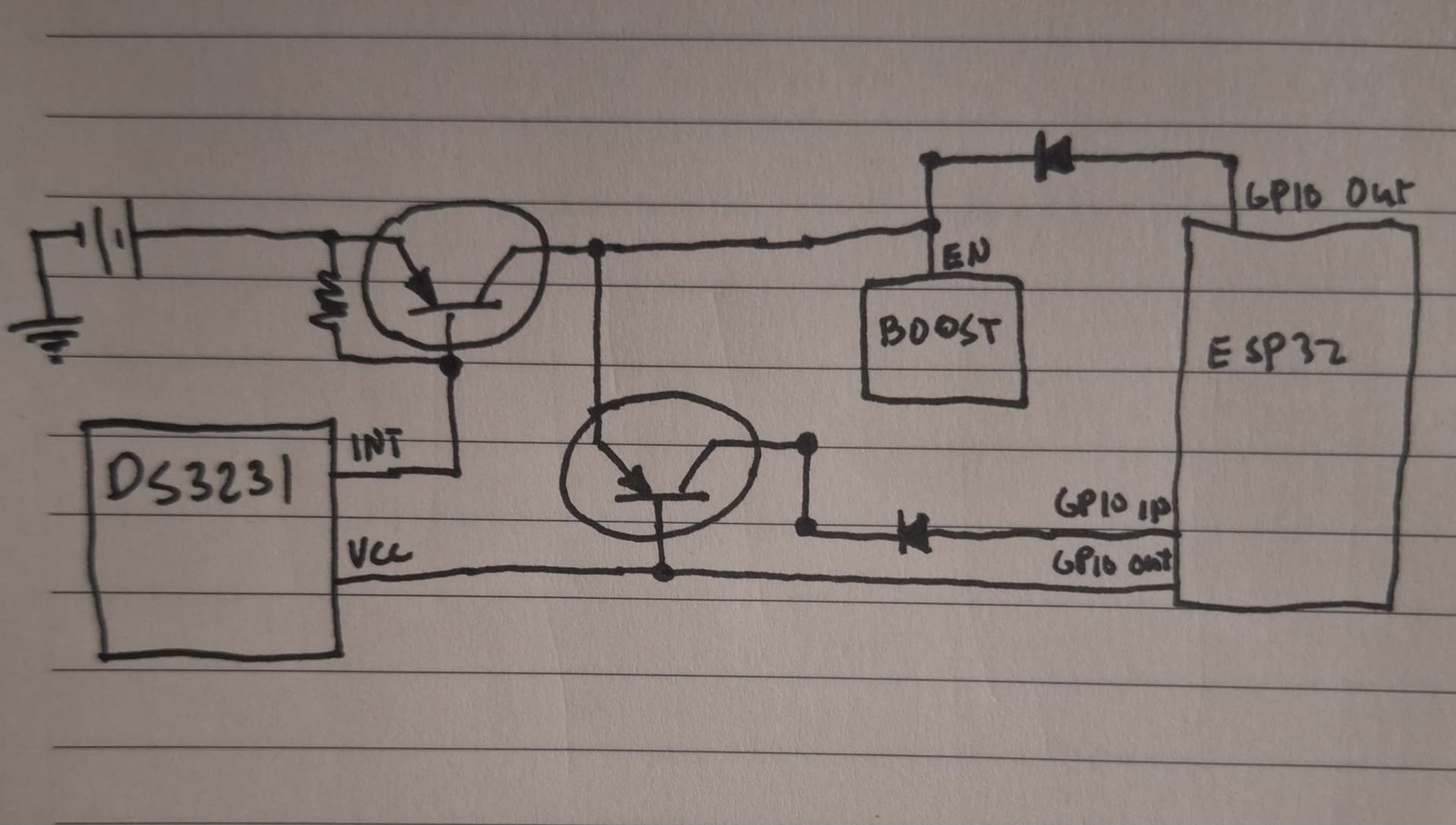
So I'm using the GPIO OUT(towards the bottom) to detect if it is already powered on, but the thing is that I'm worried that the GPIO out on the top might also be detected as an alarm since that's the one that holds the power to the whole thing. My end goal here is to turn on the EN pin with a push of a button or when an alarm is detected through the DS3231. Now when the ESP32 is powered on I will immediately clear the alarm, so the next time that the alarm goes off when the ESP32 is already on it will be detected by the ESP32(to like just turn the onboard LED or play a tone a buzzer).
PS. I will be renaming this whole post later since this expanded on a whole new problem
Sorry, you've lost me.
In a simplified manner, I still want to use the INT pin on DS3231 to be able to detect by my ESP32

I didn't know that you could that sir, I always thought that you'd need the INT pin to tell that an alarm has triggered. Thank you for your patience sir. I will be testing this then and report back if it all works together.
I think one revision with the circuit is that the NPN transistor, the collector and the emitter needs to swapped because the second time I tested it, the detecting when the button is pushed doesn't work until I swapped it. Haven't tested the circuit with ds3231 yet. Thanks again sir @ShermanP
I still don't get how it should behave like this, because from how I understand it, it should flow from Collector to Emitter, but it is the opposite, it flows from Emitter to Collector? Or maybe my BC547 has swapped pins?
You can search Google for the BC547 pinout. But I think the circuit is correct.
@ShermanP Can you help me with this problem sir? I have built the schematic, and all is working well and as per my comment above with NPN transistor, no need to switch it. The problem I'm having now is on the software side.
I have this code the alarmPolling example. This is just for turning on the ESP32. This code works fine. After uploading this code to ESP32, I have to disconnect either the SCL/SDA or the VCC on DS3231, then code works it turns on the ESP32 just fine. But changing the alarmbits from "0b00001111" to "0b00001110"(this is alarm every minute right?) doesn't seem to turn on the ESP32 anymore.
#include <DS3231.h>
#include <Wire.h>

DS3231 myRTC;
int LED_BUILTIN = 2;
int pin1 = 26;
int powerDS3231 = 23;

void setup() {
  Wire.begin();
  Serial.begin(9600);
  pinMode(powerDS3231, OUTPUT);
  digitalWrite(powerDS3231, HIGH);

  myRTC.turnOffAlarm(1);
  myRTC.enableOscillator(false, true, 0);
  myRTC.setA1Time(0, 0, 0, 0, 0b00001111, false, false, false);
  myRTC.turnOnAlarm(1);
  myRTC.checkIfAlarm(1);

  pinMode(pin1, INPUT);
  pinMode(LED_BUILTIN, OUTPUT);
  digitalWrite(LED_BUILTIN, HIGH);
}

void loop(){
  if (myRTC.checkIfAlarm(1, false)) {
    state = ~state;
    digitalWrite(LED_BUILTIN, state);
    //myRTC.checkIfAlarm(1, true);
  }
}
I'm not familiar with the library you are using, and don't know what parameters are used by SetA1time(). Can you post a link to the DS3231.h library?
@ShermanP this is the library that I used sir:
Does the code you posted blink the LED once per second? It seems you would need to un-comment the last line of the loop() for that to work, and change the LED state as well. The INT pin will not go back high unless you clear the alarm flag.
void loop(){
  if (myRTC.checkIfAlarm(1, false)) {
    state = ~state;
    digitalWrite(LED_BUILTIN, state);
    delay (100);
    state = ~state;
    digitalWrite(LED_BUILTIN, state);
    myRTC.checkIfAlarm(1, true);
  }
}
Anyway, if this works, I don't know why changing it to once per minute wouldn't work too.
@ShermanP I think my problem is that the alarm works when the DS3231 is powered on, the INT pin goes low when monitored with my multimeter. But when the DS3231 is powered off the INT is always high.
EDIT: the INT pin is already disconnected on the VCC line of DS3231, I also followed the schematics above
Do you have the /EOSC bit cleared? That's needed to keep the oscillator running when you shift to coin cell backup. Otherwise, I don't know what the problem is. If you set the alarm time and enable the alarm, then power down VCC, it should still trigger the alarm normally.