From what I can guess is he is reading the same channel for both reads. Hard to say for sure as the code is not all there. At this point to me it appears as there are three different circuits posted. This could have been answered in a few comments if the annotated schematic were posted along with the code. The solution should be simple.
Yes, Perry has all but proven this.
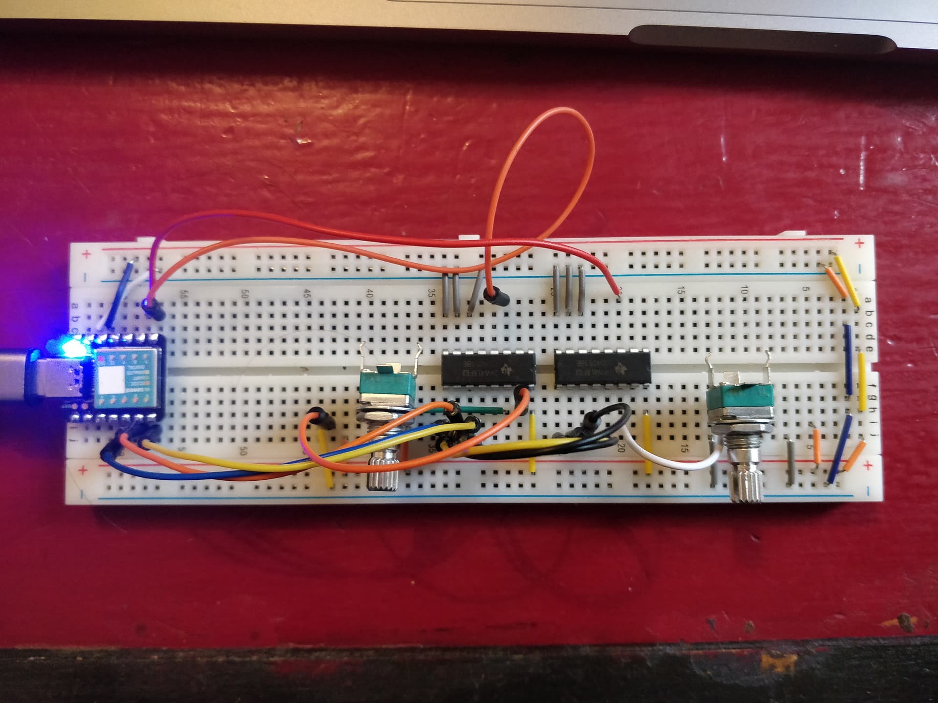
Glad to see the circuit working here !
My code
/*
  MIDIPots
*/

#include <Arduino.h>
#include "MIDIUSB.h"

// Interface ##########################################

// 4051's
const static byte MUXS_NB = 2;
const static byte SENSORS_NB = 8;

// the multiplexers address select lines (A/B/C)
const byte addressA = 6; // low-order bit
const byte addressB = 5;
const byte addressC = 4; // high-order bit

void controlChange(byte, byte, byte);
void noteOff(byte, byte, byte);
void noteOn(byte, byte, byte);
int readSensor(int, const byte);
void readSw();

void setup()
{
  Serial.begin(115200);

  pinMode(2, INPUT_PULLUP);

  pinMode(addressA, OUTPUT);
  pinMode(addressB, OUTPUT);
  pinMode(addressC, OUTPUT);
}

void loop()
{
  MidiUSB.read();
  int static previousSensorsValues[MUXS_NB][SENSORS_NB];
  int static sensorValues[MUXS_NB][SENSORS_NB];
  int cc = 0;

  // for all muxs
  for (byte i = 0; i < MUXS_NB; i++)
  {
    // show all 8 sensor readings
    for (byte j = 0; j < SENSORS_NB; j++)
    {
      sensorValues[i][j] = readSensor(i + 7, j);

      if (j == 5)
      {

        Serial.print("Sensor ");
        Serial.print(i);
        Serial.print(".");
        Serial.print(j);
        Serial.print(" reads: ");
        Serial.print(sensorValues[i][j]);
        Serial.println();
      }

      if (sensorValues[i][j] < previousSensorsValues[i][j] - 5 || sensorValues[i][j] > previousSensorsValues[i][j] + 5)
      {
        controlChange(0, cc, map(sensorValues[i][j], 1, 1023, 0, 127)); // Set the value of controller 10 on channel 0 to 65
        MidiUSB.flush();

        previousSensorsValues[i][j] = sensorValues[i][j];
      }
      // else
      // {
      //   Serial.print(sensorValues[i][j]);
      //   Serial.print(" && ");
      //   Serial.println(previousSensorsValues[i][j]);

      //   Serial.print(i);
      //   Serial.print(".");
      //   Serial.print(j);
      //   Serial.print(": ");
      //   Serial.println("not sending MIDI)");
      // }

      cc++;
      delay(150);
    }
    Serial.println();
  }
  // readSw();
}

int readSensor(int sensorPin, const byte which)
{
  // select correct MUX channel
  digitalWrite(addressA, (which & 1) ? HIGH : LOW); // low-order bit
  digitalWrite(addressB, (which & 2) ? HIGH : LOW);
  digitalWrite(addressC, (which & 4) ? HIGH : LOW); // high-order bit
  // now read the sensor
  int caca = (analogRead(sensorPin));
  caca++;
  return analogRead(sensorPin);
} // end of readSensor

void readSw()
{
  int data = digitalRead(2);
  static int previousData = data;

  if (data == LOW && data != previousData)
  {
    noteOn(0, 36, 127);
  }
}

// First parameter is the event type (0x09 = note on, 0x08 = note off).
// Second parameter is note-on/note-off, combined with the channel.
// Channel can be anything between 0-15. Typically reported to the user as 1-16.
// Third parameter is the note number (48 = middle C).
// Fourth parameter is the velocity (64 = normal, 127 = fastest).

void noteOn(byte channel, byte pitch, byte velocity)
{
  midiEventPacket_t noteOn = {0x09, 0x90 | channel, pitch, velocity};
  MidiUSB.sendMIDI(noteOn);
}

void noteOff(byte channel, byte pitch, byte velocity)
{
  midiEventPacket_t noteOff = {0x08, 0x80 | channel, pitch, velocity};
  MidiUSB.sendMIDI(noteOff);
}

// First parameter is the event type (0x0B = control change).
// Second parameter is the event type, combined with the channel.
// Third parameter is the control number number (0-119).
// Fourth parameter is the control value (0-127).

void controlChange(byte channel, byte control, byte value)
{
  midiEventPacket_t event = {0x0B, 0xB0 | channel, control, value};
  MidiUSB.sendMIDI(event);
}
What resistance do u use for the pots ?
Tomorrow gonna remake that on breadboard and keep u informed.
That might be the problem. Different logic voltages.
The Seeed Xiao uses a 3.3volt-logic SAMD21 processor.
The pots and the muxers are powered with 5volt.
OP shoves 0-5volt into a 3.3volt pin, which will (or already has) damage it.
The muxer chips migh need more than 3.3volt highs on their address pins when powered with 5volt.
The CD4051 is designed for 12volt. A 74HC4051 would have been a better choice.
Pots and muxers must be powered from the 3.3volt pin of the Xiao.
Leo..
Edit: The CD4051 has a VEE pin (7) for a negative supply, which must be grounded on a single supply.
47k. No particular reason, just what I happen to have. I would think anything between 1k and 100k would be ok.
I suggest you modify my code as little as necessary to make it work on your hardware and see what results you get.
Heys guys, some news !
@PerryBebbington your code is more better than me, so thank u for providing it to me. But your reading channel 0 on mux 0 and channel 1 on mux 1, my problem is that the channel 0 of both of muxs were affecting each other.
@Wawa u point the problem ! I make ur suggestion on breadboard and when powering the pots and muxs with the 3.3V of Xiao there is not interference anymore !
I just not understand ur last sentence
which must be grounded on a single supply.
Both muxs VEE need to be grounded to the Xiao, right ?
Anyways, the things works far better with ur suggestions, thanks guys !
I carefully modelled my connections on the Fritzing diagram you posted in reply #9. You clearly show the left hand potentiometer connected to the right hand 4051 input 1 and the right hand potentiometer connected to the left hand 4051 input 0. I now see that your Frizing diagram and your schematic in reply #16 do not match.
Thank you for the feedback on your progress, is this now solved?

Yes, you must ground it, because you use a single 3.3volt supply.
The CD4051 can also switch ground-referred AC signals, like audio. In which case VEE must be connected to a negative supply. Not relevant here, but VEE must be connected to something.
Leo..