Two Grove Digital Light Sensors on Arduino Uno R4 WiFi

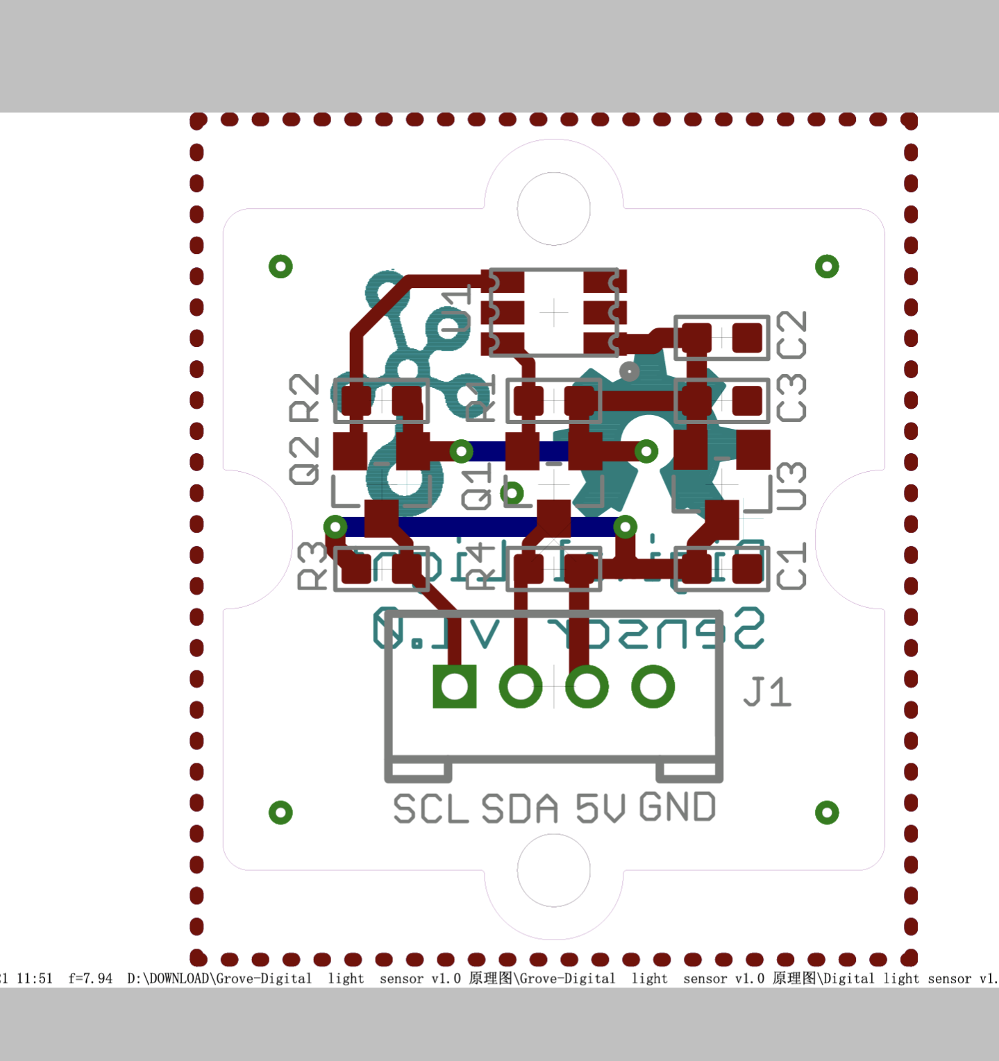
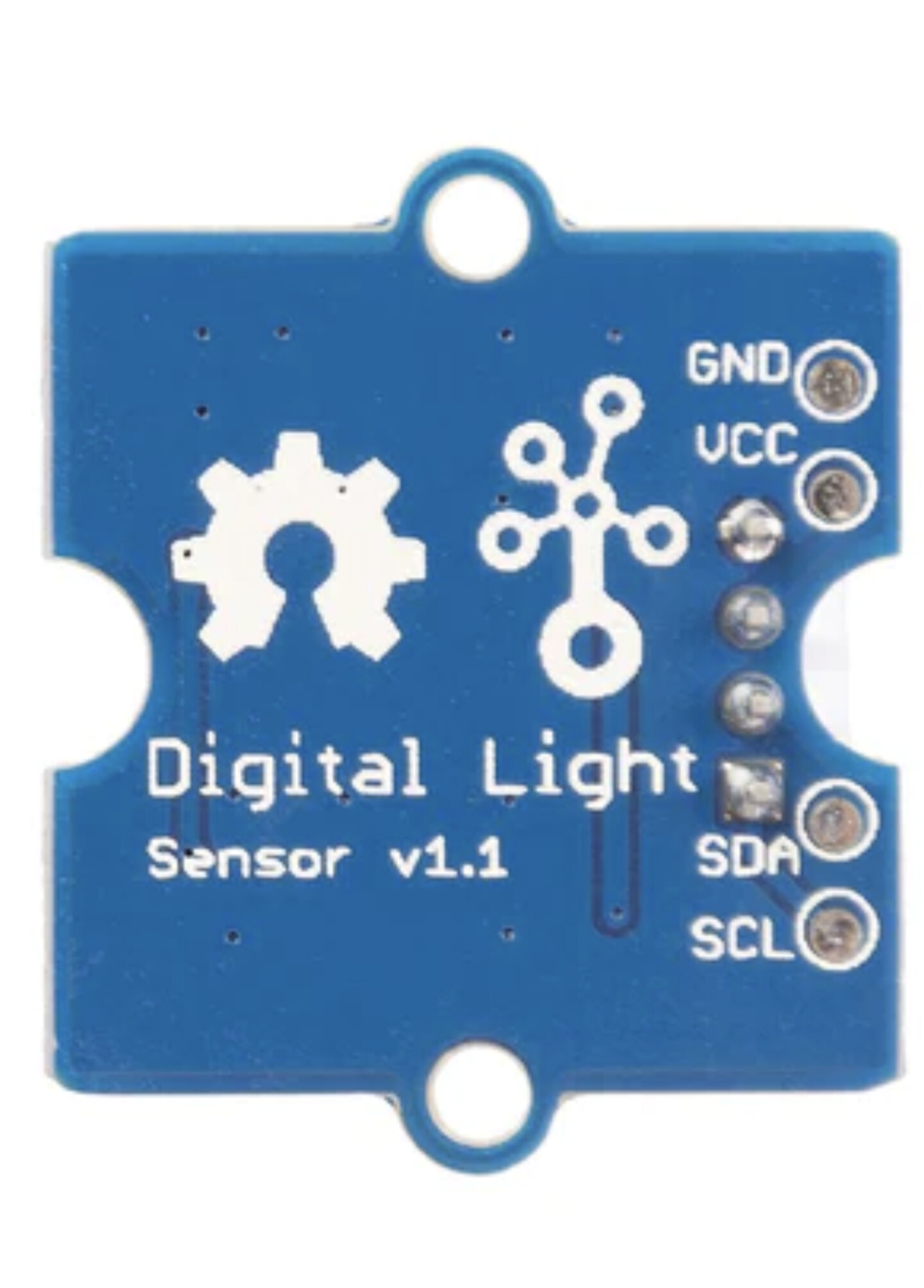
Hello, I want to use two Grove Digital Light Sensors TSL2561 on my Arduino Uno R4 WiFi. The Grove Sensor provides three addresses: 0x29, 0x39, 0x49.
Problem is how to define the addresses.

Any thoughts on my code?

#include "WiFiS3.h"
#include "index.h"
#include <Wire.h>
#include <Digital_Light_TSL2561.h>

#include "arduino_secrets.h"
///////please enter your sensitive data in the Secret tab/arduino_secrets.h
char ssid[] = SECRET_SSID;        // your network SSID (name)
char pass[] = SECRET_PASS;    // your network password 

#define RELAY_PIN_1  2 // the Arduino pin, which connects to the IN1 pin of relay module
#define RELAY_PIN_2  4 // the Arduino pin, which connects to the IN2 pin of relay module
#define RELAY_PIN_3  7 // the Arduino pin, which connects to the IN3 pin of relay module
#define RELAY_PIN_4  8 // the Arduino pin, which connects to the IN4 pin of relay module

#define TSL2561_Address_1 0x29
#define TSL2561_Address_2 0x39

TSL2561_CalculateLux tsl2561_1; //  adress 0x29
TSL2561_CalculateLux tsl2561_2; // address 0x39

// Current time
unsigned long currentTime = millis();
unsigned long previousTime = 0;
// Define timeout time in milliseconds (example: 2000ms = 2s)
const long timeoutTime = 2000;


int status = WL_IDLE_STATUS;
WiFiServer server(80);

void setup() {
  Wire.begin();
  Wire1.begin();
  Serial.begin(9600);
  tsl2561_1.init();     // Initialize tsl1 to address 0x29
  tsl2561_2.init();     // Initialize tsl2 to address 0x39
}

void loop() {
  // read values of Sensor1
  uint16_t luxSensor1 = tsl2561_1.readVisibleLux();
  if (luxSensor1 != 0xFFFF) {
    Serial.print("Sensor 1 Lux: ");
    Serial.println(luxSensor1);
  } else {
    Serial.println("Sensor 1  Error");
  }

  // read values of Sensor2
   uint16_t luxSensor2 = tsl2561_2.readVisibleLux();
  if (luxSensor2 != 0xFFFF) {
    Serial.print("Sensor 2 Lux: ");
    Serial.println(luxSensor2);
  } else {
    Serial.println("Sensor 2 Error");
  }

  delay(5000); // 5 seconds delay between measures
}


Are there any examples with the library ?

if you look at the TSL2561 datasheet the module has a ADDR_SEL pin which is used to select the I2C address

TSL2561pinout

Pin 2 of the TSL2561 is the ADDR SEL pin that is used to select the address.

TSL2561 address selection

You connect ADDR SEL to GND to select address 0x29,
leave ADDR SEL floating/open circuit for address 0x39,
or connect ADDR SEL to +5V to select address 0x49.

However looking at the Grove Digital Light Sensor Schematic it looks as though the ADDR SEL pin is permanantly connected to GND.

If that is the case, then you would need to modify the PCB to change the address.

Not really.
Just for one sensor and that's very easy.


The code looks as though it is already written to expect one TSL2561 at address 0x29, and one at 0x39.

One of the two modules has to have its address changed by disconnecting pin2 from GND, and leaving it floating.

Yes. But is simply desoldering pin 2 the only way?

It might be possible to cut the PCB trace with a sharp scalpel to the left of pin 2 to isolate that pin.

Make two parallel cuts as shown in yellow below, and remove the copper between the cuts.

I can't be sure whether that is feasible or not from the photo of the PCB.

The PCB layout does not agree with the photograph.

There is a ground plane on the PCB that does not show up on the PCB layout.
It is clearly missing from the layout because the GND pin on the connecor appears to be unconnected.
I've looked at the Eagle files too, and they are the same.

There may be other differences too, it looks like the sensor itself has been turned through 180 degrees.

Double check before cutting, if you decide to go that way.

I will give it a try. I'm owning a few sensors.

This topic was automatically closed 180 days after the last reply. New replies are no longer allowed.