With 6 relays OFF-ON inter-locked for sensors by reading A0, A1, A2, A3, A4, A5
for A0 output D2 or D3
for A1 output D4 or D5
for A2 output D6 or D7
for A3 output D8 or D9
for A4 output only D10
for A5 output only D11
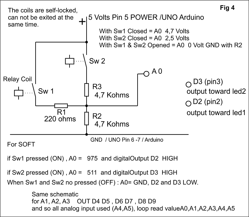
The function "or" is realised by select SW closed and reading Voltage on A0
idem for A1, A2, A3.
For A4, A5, when relay closed the level voltage is 2,5V with the two resistors.
Output:
Digital output, 8 leds level Hight to optotransistors
D2, or D3 for A0 by SW selected LEDs Hights
D4, or D5 for A1 by SW selected
D6, or D7 for A2 by SW selected
D8, or D9 for A3 by SW selected
D10 for A4 LED Hignt
D11 for A5 LED Hight
``/test in a first time with input analog level A0 and
D2 D3 output for two LEDs with Resistors 220R. A0 is switched with
two Relays SW1 and SW2; see up schematic/
john35S:
/test in a first time with input analog level A0 and
D2 D3 output for two LEDs with Resistors 220R. A0 is switched with
two Relays SW1 and SW2; see up schematic/
//written by John - GIBRALTAR.
//For water pump speed variator UNO Board USED.
Serial.begin(9600);
What matters is the current that flows though the pin. Having a pin at 0V doesn't necessarily make it less than having the pin at 5V. It can go both ways.
//in first time with Switchs on A0 read the level, and the output D2 or D3 in accordance with the voltage readed
//declare the pins used
void setup(){
01 pinMode(2,OUTPUT); // out D2 for LED1 when pin2 is High
02 pinMode(3,OUTPUT); // out D3 for LED2 when pin3 is High
03 digitalWrite(2, LOW); // STATE LOW for LED1
04 digitalWrite(3, LOW); // STATE LOW for LED2
05 int port1= A0;
06 int value= 0;
07 float vin=0;
08 Serial.begin(9600);
}
//after ok I repeat that for A1 so A2 A3 A4 A5 with LED(s) out D4 D5 D6 D7 D8 D9 D10 D11
void loop(){
09 value=analogRead (port1); // read analog input A0
10 vin =(value 5000/1023; // convert level input in Volt
11 SerialprintIn(vin);
12 if(vin>3.5){
13 digitalwrite(2,HIGH); // LED1 switched ON
14 }
15 else{
16 digitalWrite(2,LOW);
17 if(vin< 3.5){
18 digitalWrite(3,HIGH); // LED2 switched ON
19 }
20 else{
21 digitalWrite(3,LOW);
22 }
23 }
// LOOP TO A1 same process
You can modify
Nelson
Modification line 10 WRITE 5000.0 no 5000
Nelson with TKS wvmarle
In the volt calculation use 5000.0/1023 to make the compiler to use floating point operations rather than integer operations.
There's no reason to calculate volts; you can just as well use the analogRead() value directly. Saves yourself that expensive floating point calculation (several hundreds of bytes of compiled code vs. just a few bytes - and execution times to match of course).