Ultra-small Arduino

Hi!

I'm not certain where to post this, so mods are free to relocate it or yeah... smack me over the head with a cod and point me to wherever...

I find that I have a small problem...
very small in fact.

My hobbies include painting miniatures, and sticking LEDs in them. And now I want to make the LEDs flash, brighten and dim in patterns, not just shine with the same brightness all the time.
So what is the issue?

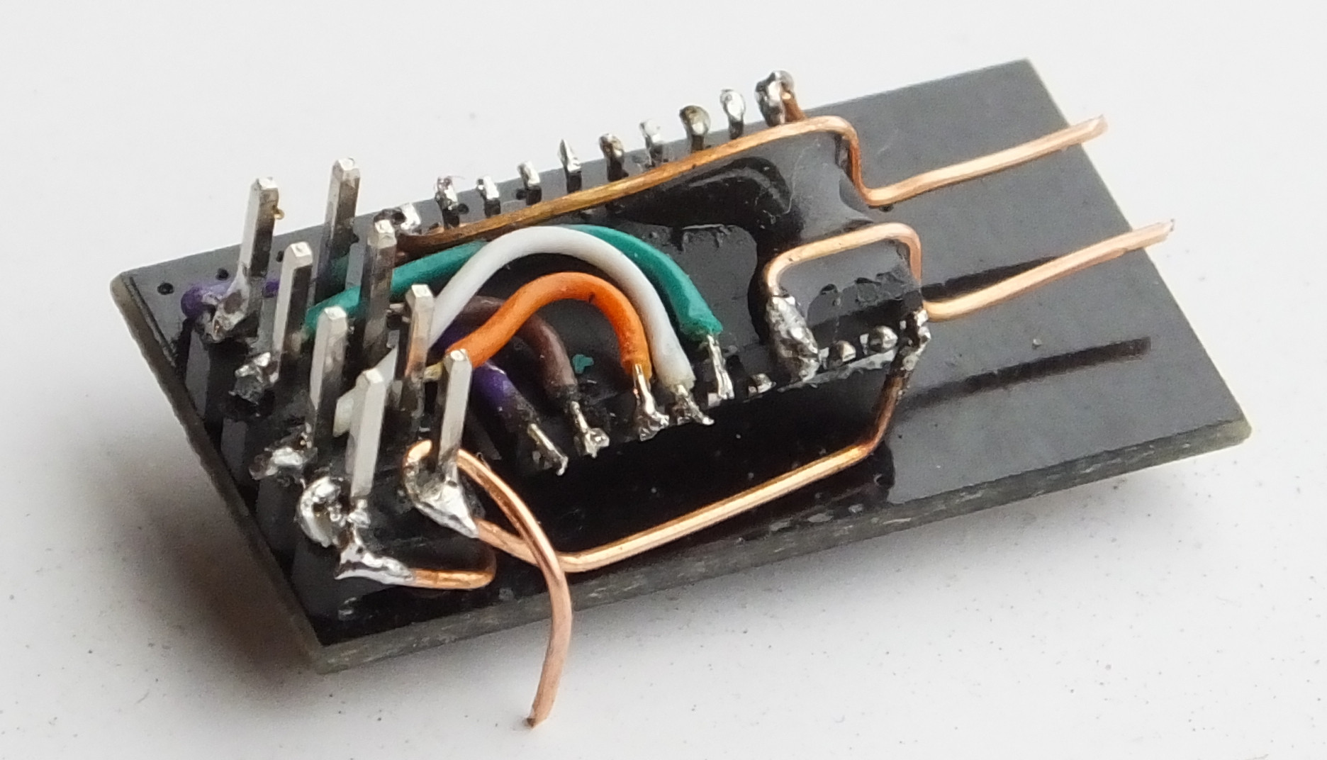
I need to fit a MCU and a battery under a typical miniature base.
(A 25mm base has about 22mm ID, and about 2.5mm inside height)

The smallest I've found is the TinyLily, which is about 14mm in diameter.
That doesn't leave me room for a proper battery such as a CR1220, so if I want to use that I'll have to use a pair of smaller Silver Oxide batteries, or go for a larger base.
The Silver Oxide batteries have issues, and a larger base looks unnatural on single minis.

So I would like to make an Arduino compatible that's half-moon shaped, so that it fits around the battery, and have connectors on the outside edge.

The connectors would be half-circle cutouts as if you after drilling and plating holes, cut away the outer edge, bisecting the holes.
(This should save at least 1mm diameter.

For programming I was thinking an adapter somewhat like the one used for the TinyLily, but with pogo pins.

I learned programming a long time ago, even did some assembly on some 8bit platforms(6502, Z80, 8051) and some high-level languages, Pascal, ADA, C, even C++ (C++ is not something I want to mess with again... ) but the relative simplicity of the Arduino seems best suited for this.

What is the smallest MCU currently supported by the Arduino toolchain?
(either length or widt of package + pins. )

If there's nothing smaller than the AtMega328p, how much work is it to re-tool for a smaller chip?
(The ATtiny814 SOIC150 is slightly smaller along one side. Yes, I'm desperate for space. )

I can solder 0805 SMT without too much issue, and have even done 0603 once, so assembling a board or three should be no issue.
I don't have reflow tools, so BGA or other packages with contacts underneath is not an option for me.
(If anyone else wants to grab the idea and make a production run, feel free, but I doubt the market is large enough for it to be profitable)

ATTiny85 come in an SOIC-8 package , which is like 5mm x 5mm or so. If you can hand solder 0805 you should have no problem with SOIC-8

A frypan on the stove is surprisingly effective for soldering SMD if you use leaded solder paste. It heats the PCB from the bottom so easily-melted parts like plastic connectors don't melt.

Buy an infrared thermometer and do a few test runs to work out which setting on the burner knob to use. I put my electric stove on #7 and pull the pan off when the solder goes shiney.

Obviously don't use the frypan you cook breakfast in. Buy your cook a new one and use the old scratched one for soldering.

Professional PCBs make the process infinitely easier by using good soldermask. For that size you can probably get 3 next week as a rush job for $3 or 20 of them in a month for the same price.

Ideally, I'd like a couple more IO than the ATtiny85 but I guess that could be used.

Now, if I could solder the TSSOP package... it would seriously open opportunities.
(There are 20mm bases in use, also... Or possibly as a thin stick)

The frying pan idea is something I may have to look into.
I 'baked' some HP formatter boards from LJ2420 and LJ3005 printers way back then in the oven.
(place the card component side up, on a couple of balls of tinfoil, on a metal tray, 200degrees C for 5 - 10 minutes.)
Those were some of the first HPs with lead-free solder, and they had serious issues with the large BGA chips on them. About 2 out of 3 cards worked OK afterwards.

I will be looking at pro services to produce the prints since I have no chance of making a double sided PCB with through-holes or plated holes.

Any open space left over between the Half-moon PCB and the battery will be for resistors(not going to have resistors for the LEDs on the PCB since I might want to use the IO for other things also), REED relays switches and other fun stuff.

I really want people to look at my minis and ask 'How the ***** did you DO THAT!?'

And since my painting skills aren't up to that...

Have you tried "dead bug soldering" to a DIP chip? I would embed the chip and LEDs into the model and only have the battery in the base.

A couple of shiny spots on the model can be connections for programming: put TX on the nose of the left warp nacelle, for example.

I'm not building that kind of minis....

It's Dungeons & Dragons, that kind of stuff.

There's not all that much space in a skeleton in 28mm scale to stuff a DIP.

You can see one of my first conversions here;

Note, 28mm scale means a typical male human in that scale would be 28mm from the soles of his boots, to his eyes, or about 1:56.

That one was made of soft plastic, so it was relatively easy to drill or cut,
Most are made of pewter, and would be a real pain to hollow out, even if you could find a place to 'go in' that wouldn't damage details.

about ATtiny85, I see that one isn't available in TSSOP8, so that crused THAT dream.
(I expect the 45 doesn't have enough Flash area to be usable?)
So I guess I'll stick to SOIC-8

Ok. That forum post helps get the picture across.

I just saw yesterday that Adafruit sells a ZIF socket for SOIC-8 so you can program the chip before soldering. That saves a gigantic amount of space on the PCB by omitting the progamming header.

Then maybe dead-bug solder to the SOIC chip? But a PCB will likely end up smaller and obviously more reliable. OSH Park has an option for 0.8mm (half thickness) PCBs and their new flexible PCB service is even thinner.

Couldn't you stack a 20mm round circuit board on top of a 20mm battery (cr2016?)
That gives you a lot of room to work with; you just need to figure out out to make it as thin as possible, which is probably easier than the crescent-shaped PCB idea.

MorganS:
Ok. That forum post helps get the picture across.

I just saw yesterday that Adafruit sells a ZIF socket for SOIC-8 so you can program the chip before soldering. That saves a gigantic amount of space on the PCB by omitting the progamming header.

Then maybe dead-bug solder to the SOIC chip? But a PCB will likely end up smaller and obviously more reliable. OSH Park has an option for 0.8mm (half thickness) PCBs and their new flexible PCB service is even thinner.

Adafruit has a lot of nice stuff... but some things are way overpriced there.
dead-bug oldering is an option, but only for one or two minis.

westfw:
Couldn't you stack a 20mm round circuit board on top of a 20mm battery (cr2016?)
That gives you a lot of room to work with; you just need to figure out out to make it as thin as possible, which is probably easier than the crescent-shaped PCB idea.

A CR2016 is 1.6mm thick. That leaves me with 0.9mm thickness for the PCB and components.
(Less really, because I need to connect the battery, also)
A TinyLily, using a PQsomething package chip and ignoring the programming connector is 1.5mm thick.
And they're using a 0.6mm PCB.
Its possible to go down to a 0.4mm PCB, but still...
A SOIC package is between 1.35 - 1.7mm high.

Well for just 7 colour flashing there is 3m leds at £1 uk for 10 !

https://www.ebay.co.uk/itm/3-5-10mm-Ultra-Bright-3V-Clear-RGB-LED-Bulbs-7-Colour-Flash-Flashing/391106601522?hash=item5b0fc52232:m:mdWbfOb9CiQC3X64z_q_CBQ:rk:20:pf:0

you're funny...

:wink:

Take a look at the link I posted.
The head of the skeletal mini is smaller than many matchstick heads.

I use anything from 0402 to 1206 LEDs with presoldered wires to get them to fit.

and a steady blink is boring.
I want to make custom patterns, even synchronize effects across multiple LEDs

Imagine a sword with a 'running light' along the blade, then fades down to an even, ominous glow before returning to running lights again. That's one of many I want to be able to do, but can't right now because there's not enough room.

:o I'll get my coat.......

Nah, stick around. This might end up being fun.

An attiny85 can drive 20 leds pretty easily, with charlieplexing.
(Not sure how well they’d fade, with that scheme.)
There are those 6pin sot23 chips. I’d think that if there is support for attiny13, the tiny10 ought not be too much of a stretch.

Gadgetman:
A CR2016 is 1.6mm thick. That leaves me with 0.9mm thickness for the PCB and components.

Don't use a PCB. Just solder wires directly to the chip. Think about gluing the chip upside-down on the battery. I have done that with Attiny's - but my examples would be too big for you.


I built another one using lacquered wire (as used in transformers) .

To be honest, I suspect you are deluding yourself if you expect a DIY solution that will fit in a depth of 0.9mm. Why not use a different battery that leaves you more empty space?

Can some of the electronics fit inside the thing that is above the base?

...R

Do they need to light up anywhere, or is it ok if they light up as long as they're sitting in a certain place? If the latter, then maybe it could be possible to power them inductively?
I've never done this, only seen my toothbrush do it.
A coil could be wound that leaves space in the center for the electronics. The electronics shouldn't be disturbed by the directly induced voltages, if it takes a coil of many turns to get the desired voltage.

Robin2:
Don't use a PCB. Just solder wires directly to the chip. Think about gluing the chip upside-down on the battery. I have done that with Attiny's - but my examples would be too big for you.


I built another one using lacquered wire (as used in transformers) .

To be honest, I suspect you are deluding yourself if you expect a DIY solution that will fit in a depth of 0.9mm. Why not use a different battery that leaves you more empty space?

Can some of the electronics fit inside the thing that is above the base?

...R

Soldering directly has been mentioned already. It's called Dead bug soldering.
It's something I could consider for one off, but I want it to look reasonably professional(I sometimes give them away)

I have a volume that's 22mm in diameter, and 2.5mm high. By using a 'half-moon' or crescent shape PCB I can have a decent size batter (CR1220) and still fit the electronics.

Did you check the link?
These are 28mm / 1:56 scale miniatures, mostly humans or humanoids.
There is NO ROOM inside them. And on most that are large enough, it's not possible to hollow them out sufficiently without doing damage to visible portions.

I prefer to stay away from laquered wires if can, but that may be just me. They wouldn't give me much more clearance from the wires I already use. (I'm working with metal minis. I may need to drill holes to meet at an angle inside a body, and I'm worried about scraping off some of the laquer. Probably not much of an issue. But with a 0.5 or 0.8mm hole there's plenty of room for insulated wires... )

GalFisk:
Do they need to light up anywhere, or is it ok if they light up as long as they're sitting in a certain place? If the latter, then maybe it could be possible to power them inductively?
I've never done this, only seen my toothbrush do it.
A coil could be wound that leaves space in the center for the electronics. The electronics shouldn't be disturbed by the directly induced voltages, if it takes a coil of many turns to get the desired voltage.

Inductive power is something I've been considering, but it requires a second base.
I want them to be indistinguishable from a normal mini until they light up.

At least I'm not thinking of adding sound...

Find a greeting card with LEDs or sound. Steal the electronics from that.

Please, NO!

One day I'll track down the creator of those cards, and dance on his grave.
If he's still alive...

I'll bring a shovel...

I've decided to order a couple of ATtiny13 and 85 in different packages(including regular DIP) and some 'adapter' PCBs that takes different type SMTs and expand them out to DIP.

That should be good for getting me started Cakeboarding, to try my hand at different SMT soldering.

I need to decide on a programmer, also.
no hurry. It's a hobby after all.