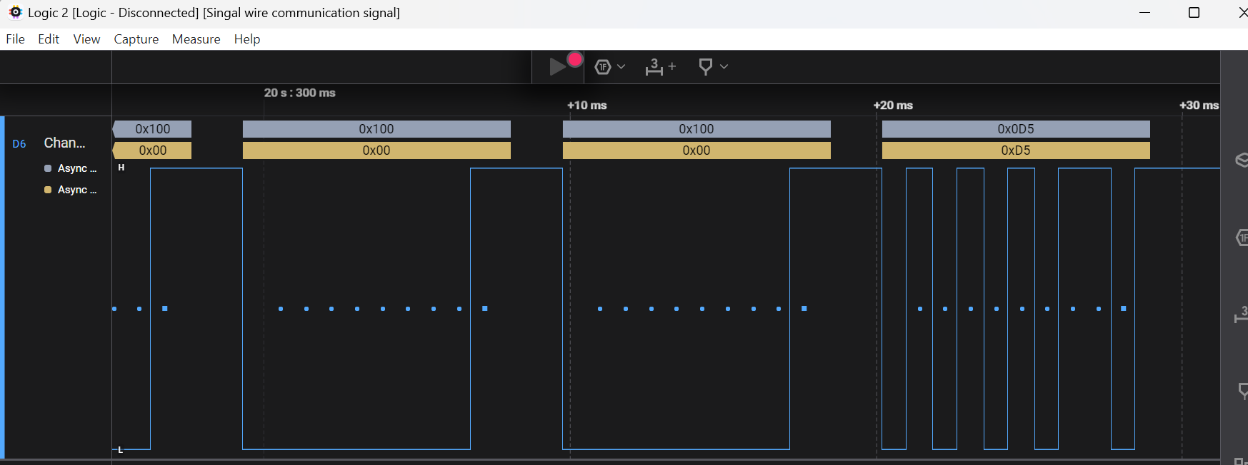
Hi there, i am working on a reverse engineering project . My problem is that, i have a device that commnicates via signal wire . I have found out that it is UART signal and also found a baudrate manually(1200 bps ). Now the problem is i cannot figure out the frame format of the commnication. I have captured the signal in saleac logic analyser and used the in-buit UART protocal analyser but 2 configartion mathes the signal without any framing error, or parity error.So i dont know which is the proper configuration.
Configuration:
Baudrate = 1200bps
Startbit + 8bit data + odd parity + 1 or 1.5 or 2 stop bits
Startbit + 9bit data + even parity + 1 or 1.5 or 2 stop bits
i have attached the logic analyser files here below:
Can anyone help me out understand the frame format. thank you.
But as per the single transition representing "1". The time of high transition 832 microseconds and the formula to find baudrate is 1/time of single transition. So i decided that it must be 1200bps. But if u have any new approch i am ready to study further. thank you
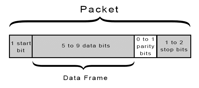
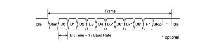
This is how UART transmitted data is organized: It is organized into packets that have one start bit, 5 to 9 data bits. A parity bit is optional, and 2 stop bits.
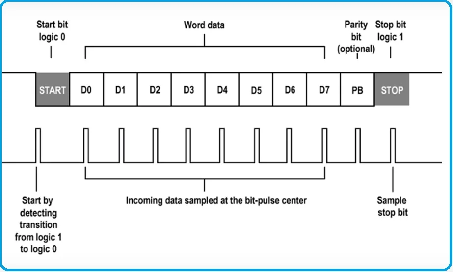
Start Bit: When not transmitting data the UART data transmission line is usually high voltage. In order to start the transfer process the transmitting UART switches from high voltage to low voltage for one clock cycle. The receiving UART will detect the high to low voltage transition and start reading the bits at the accurate baud rate. Note many of the serial line drivers reverse the polarity as they are inverting.
Parity: Parity is the oddness or evenness of a number. The parity bit functions to tell the receiving UART if the data has changed during transmission. Bits can change due to electromagnetism, different baud rates or long-distance transmission of data. The UART reads the data frame after receiving the data. It then counts the number of bits and checks if they are even or odd. If the parity bit is a 0 then it is even parity. If the bit is a 1 then it is an odd parity. For the UART to know that the transmission is free of errors the parity bit has to match the data. You can also transmit without the parity bit.
Stop bits: For at least two-bit duration the transmitting UART drives the transmission line from a low to a high voltage. I always sent with two stops bits and received with 1, this gave me one extra bit time to minimize data skewing.
Baud Rate: The communication between two devices via UART Protocol occurs by transmission of bits. A total of 8 bits are sent one right after the other to transmit a byte. A bit is either a logical low or high. The time interval between two bits is called the baud rate or bit rate. The baud rate must be defined in both transmit and receive devices. This allows the sending device to encode the data into bit pattern with the specific time interval. There is an allowable tolerance in the baud clock. Note the faster the baud the narrow the time tolerance becomes. It is important that the receiver gets the successive bits at the right time.
The most commonly used baud rates is 9600 bits per second. Although other baud rates are also used, but the higher the bit rate, the more chances there are of data corruption. Lower bit rates are used when there is greater physical distance between two devices because the length of the wire increases resistance and thus deteriorates the signal.
9600 8N1 - 9600 baud, 8 data bits, no parity, and 1 stop bit - is one of the more commonly used serial protocols. This can be in a slightly different format but it indicates the same. For 1200 baud it would be 12 8N1.
Sorry, but I prefer not to download applications to my laptop to view files. It might be better to post images. I don't know how many readers of this topic will already have a way to view the files.
As u explained the uart frame structure I got some more information about parity.
But how do I confirm which configuration is the correct for the frame I am working.
You may carry out the following steps to see if the incoming farme agrees with: 1-StartBit, 8 Charcater bits, Odd party, 1-Stopit, and Bd = 1200. This sketch will turn on the onboard LED of Arduino UNO if there is a parity mismatch.
1. Upload the following sketch (compiled but NOT tested) into Arduino UNO.
#define LED 13
char ch;

void setup()
{
  UCSR0A = 0x00;                           //reset; Bd factor is not doubled,
  UCSR0B |= (1 << RXEN0) | (1 << TXEN0);  //Serial transmitter/receiver are enabled
  UCSR0C |= bit(UCSZ01) | bit(UCSZ00)|bit(UPM01)|bit(UPM00); //8-bit charcater size, 1-StopBit, odd parity
  UBRR0 = 6666; //Bd = 1200 using this Eqn: UBRR0 = (fosc/2xBd)-1
  pinMode(LED, OUTPUT);
}

void loop()
{
  while (bitRead(UCSR0A, RXC0) != HIGH)//check if RXC0flag HIGH indicating data ready
  {
    ;
  }
  ch = UDR0;  //read the arrived data from Recievr, TXC0 flag is cleared
  if (bitRead(UCSR0A, UPE0) == HIGH)
  {
    digitalWrite(LED, HIGH); //parity mismatch
    delay(2000); //remain ON for 2-sec
    digitalWrite(LED, LOW);
  }
}
2. Disconnect the UNO from the PC. 3. Cnnect your device with Hardware UART Port (RX, TX) of Arduino UNO using RS232 <---->TTL converter if needed. Do not forget to connect the common GND of your device and UNO.
4. Apply 7V to 12V Supply at the Barrel Jack of UNO. 5. Power on your device. 6. Press RESET Button of UNO, 7. Check if LED is off which indicates some progress of the experiment. 8. If you want to monitor the incoming characters coming from your device in the Serial Monitor, create a Soft UART Port and interfcae it with PC's USB Port using RS232<---->TTL Converter.
It may even help you figure out the process if, for example, it is a request response and it is using an address to ping the sensor and you know said address, then hopefully you may figure how to match the HI's an LO's to the address
hope that helps....
PS: if you give some details of the equipment you are trying to reverse engineer, who knows maybe someone here already did that!
Can you measure the time between adjacent start bits?
For the 2nd possibility, is the parity bit always the same level as the stop bits? If so, then the first option is likely the correct choice.
the stopbit IMHO is irrelevant in the sense that setting stopbit=1, you can insert a delay between transmissions if required.
my money is on option 1...