Have a real issue I'm struggling with here and could really do with some help with it! I'm very new to both electronic bits and programming, but certainly getting there already. I am trying to create a set of "presets " for moving a geared dc motor within the same sketch, which will then be able to be selected via an LCD and it's buttons.
The issue I'm having is twofold. First, getting the linksprite motor shield to work alongside a linksprite 16x2 LCD. Both codes work on each item respectively, such as the menu system on the LCD and the motor control. But I physically cannot get the motor shield, LCD and uno linked up, let alone the codes written to work together. I think the issue may be with the puns, but from memory (at work atm so notes not to hand) there are a few pins spare but can't work out how to change them (if that's even possible)
I do have a few breadboard, lots of jumper wires plus the linksprite proto shield for if I can get it running!
The motor shield with the L293D uses almost every pin. Perhaps the analog pins and pin 2 are just enough to make it work.
Do you also have some buttons ?
Newer motors shields are much better (with mosfet outputs) and use less pins. There are also LCD displays that use only 2 pins of the I2C bus. But I think with a little pin-shuffling you should be able to make this work.
The LCD does have buttons which I want to be able to use to move through a menu system (which I have a basic code for) and select a different speed/action for the motor. I'm. Only running one dc and for only 1500m/s.
The motor shield runs using very few pins tbh, but they seem to be being used by the LCD and the pin shuffling is a definite answer to this I think, but something I'm struggling with!
Your display uses: 8, 13, 9, 4, 5, 6, 7 for the lcd and A0 for the buttons.
Your motor shield uses: 3, 4, 5, 6, 7, 8, 9, 10, 11, 12 (pin 9 and 10 only for the servo connectors).
So it is impossible to combine those.
You could rewire everything on the lcd shield to make it work.
The motor shield does not use pin 2 and 13 and also not A0 to A5. So it is possible to make them both work on the same Arduino board...
I'll apologise for all the questions in advance but when you rewire, in what way would you suggest?
I have tried via the code but nothing seemed to work. As I definitely need the buttons, I'm loathed to remove the LCD from the shield too (if that makes sense or is involved)
Definitely tempted to pick up a different LCD but time is running out to get this done for Friday! Even if I can get this one rolling just for the weekend then pick an adafruit up next week would be good!
I suggest to buy that I2C display anyway. It only uses the I2C bus, that is A4 and A5 on the Arduino Uno.
With rewiring, I ment cutting the copper traces of the pcb board and solder wires to use new pins. It is easy to make a mistake with that, so I don't recommend it. But if you have to, it is possible.
At the moment they share too many pins. It is also not possible to make it work even a little. You might damage something. Don't try both shields as they are now. Let's hope that the Uno and the shields are not damaged.
Yep, cutting etc sounds above my skill level at the moment!! I don't think they are, I've had the Uno and motor shield running to test a code out for the last two and a half hours and seems good to me!
So with the new LCD, I can stack that onto the uno (unable to do so with the motor shield as the heat sink is too large, and no female pins on top either) then can jump across to breadboard/protoshield from the LCD to power and control the motor shield i assume?
That Adafruit LCD shield should be on top. There are no headers to add a second shield. They are also not on the motor shields. Because of the heatsink, they can't be used together
I think I made a mistake. Sorry !
Which motor shield do you have ?
I was talking about the motor shield with the L293D.
Do you have the motor shield with the L298N ? Because that one has the heatsink.
That one uses digital pin 8, 9, 10, 11, 12, 13.
So you can cut traces on your LCD shield. Cut the traces to pin 8, 9, 13 and use wires to other pins. For examples A1, A2, A3.
Or you can bend the pins of the motor shield. Also pin 8, 9, 13. After the bending, connect 8, 9, 13 of the motor shield to unused pins, that might also be A1, A2, A3. And adapt the sketch to use those new pins.
Here is a photo of bending pins : http://mcukits.com/2009/04/06/arduino-ethernet-shield-mega-hack/ (scroll down a little).
You could also cut those pins, or use a solder iron to remove them.
So i can (in theory) say keep the LCD as it is, then bend the three motor shield pins out so they won't connect at all, then jig the sketch to three un-used pins from the other side that aren't being used by the LCD?
I have already ordered the new LCD, but I'll try this in the meantime (a good learning curve for me!) and the new looks a much better build quality anyway :
As the motor shield is staying with me (for now at least!) I'll try bending the LCD i think...then mount the jumpers from the top to a breadboard and see what happens...
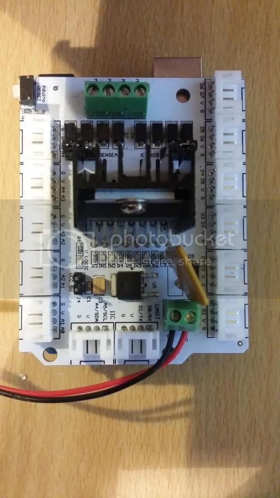
Can you make a photo of it, before turning the power on ?
Bending the LCD pins doesn't help, the shared pins (8,9,13) of the motor shield will still be conntected to those pins on LCD shield.
There is more confusion: In the example sketch, they use pin 13 for RW to the LCD. However, in the schematic pin 13 is not used, RW is tied to GND, and pin 10 is used to turn the backlight on and off with a transistor Q1.
So it might be that 8,9,13 are shared with the two shield, but it might also be 8,9,10.
Since I see a transistor Q1 on the photo, I think that the example sketch is old, and the schematic and photo are new. So I think now that is 8,9,10 that are shared.
Do you have a multimeter ?
Since pin 8 and 9 go directly to RS and E of the LCD display, you can remove the connection from the LCD module to the pcd board of the shield. Remove those short pieces of wire and solder a new wire from the RS and E on the LCD module to the new pins on the shield.
Use a multimeter to check if you need to change pin 10 or 13 (or both).
For pin 10, do you see R7 and R8 somewhere on the LCD shield ? They make the backlight turn on, but are also connected to D10.
Hi Peter. I can get a photo of it later today when I'm home from work and will post it up.
I must admit, I'm completely perplexed by this now!
I do have a multi meter at home, and I'll have a look at it all again when I get in. A week or so ago, I posted on the linksprite forum but have had nothing helpful really answered.
With the Shields connected as discussed last night I'm only getting one led on the motor shield light up, which I think from memory was the vlogic green led. There is a red led under in2 I think, when the shield is actually running and rigged correctly.