UNO RS485 communication between master and slave

Hello,

I am trying to send commands from a master arduino to a slave arduino, both UNOs, using MAX485 modules (TLL to RS485, 8 pins). I am using SoftwareSerial because of issues with hardwareSerial (RX (pin 0) and TX (pin 1) not working when the rs485 module is connected to them, even preventing me from uploading code to the arduino). Simply trying to make an LED blink for now.

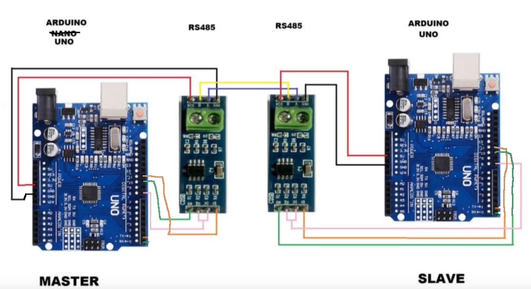
Here is the code for both arduinos as well as the wiring diagram. Both arduinos are powered via the barrel plugs (9v) or from the USB cable when I'm trying to debug the setup. My issue is that the command "A" is simply not being sent and I can't understand why. I'm not getting confirmation from my debugging lines in the serial monitor.

This is slightly modified from a tutorial I found on youtube: https://www.youtube.com/watch?v=ZR9QEWpGEDo

master code

#include <SoftwareSerial.h>

#define MASTER_EN 8       // RS485 Enable Pin
#define RX 10             // SoftwareSerial RX
#define TX 11             // SoftwareSerial TX

SoftwareSerial rs485Serial(RX, TX); // Create SoftwareSerial instance

void setup() {
  pinMode(MASTER_EN, OUTPUT);
  rs485Serial.begin(9600);
  digitalWrite(MASTER_EN, LOW);
}

void loop() {
  digitalWrite(MASTER_EN, HIGH);     // Enable transmit mode
  delay(10);                          // 5ms minimum delay

  rs485Serial.write('A');            // Send character
  rs485Serial.flush();              // Wait until data is sent

  digitalWrite(MASTER_EN, LOW);      // Back to receive mode
  delay(1000);                       // Wait before next send
}

slave code

#include <SoftwareSerial.h>

#define SLAVE_EN 8         // RS485 Enable Pin (DE/RE)
#define LED 13             // On-board LED
#define RS485_RX 10        // SoftwareSerial RX
#define RS485_TX 11        // SoftwareSerial TX

SoftwareSerial rs485(RS485_RX, RS485_TX); // RX, TX

void setup() {
  pinMode(SLAVE_EN, OUTPUT);
  pinMode(LED, OUTPUT);
  digitalWrite(SLAVE_EN, LOW);  // Set to receive mode

  rs485.begin(9600);     // RS485 communication
  Serial.begin(9600);    // Optional: for debugging via Serial Monitor
}

void loop() {
  if (rs485.available()) {
    char incoming = rs485.read();
    if (incoming == 'A') {
      digitalWrite(LED, !digitalRead(LED)); // Toggle LED
      Serial.println("Received: A");        // Debug info
      delay(100);
    }
  }
}

Do not use 9V, use USB or a wall wart or power brick. A YouTube video is not very useful; you can't copy/paste from that, and there needs to be a blog or similar.
How much power do the RS485 boards use, min, avg, max? If it exceeds the UNO pin 20mA, it won't work (it may be higher, but I can't find it)

Check if there is something wrong with your wiring.
I assembled your project here on my workbench and it worked correctly.

Also check if your IDE serial is 9600.

I powered the Arduinos via USB.

See serial printout.

Received: A
Received: A
Received: A
Received: A
Received: A
Received: A
Received: A
Received: A
Received: A
Received: A
Received: A
Received: A
Received: A
Received: A
Received: A
Received: A
Received: A
Received: A
Received: A
Received: A
Received: A

It is working as I would expect, not very well. What is the reference point for the signals. Generally it is ground which is not connected. The 9V smoke detector batteries are great for the seller, lousy for powering an Arduino. You might want to get a case of them to start. Using a Wall Wart will pay for itself before the box of batteries is not used,

Thanks for your answer, the fact you made it work immediately is reassuring.

I have checked my wiring again, tested both the arduinos' and the rs485 modules' pins for damage and changed the way I power my setup (USB, like you did) and it still doesn't work. I can confirm the master is sending something, but the slave is not receiving anything.

Could you send pictures or give advice on how you built the setup?

Thank you again for your help.

I have already "dismantled" my assembly.

Send photos of your assembly with details, so we can look at it and see if we can identify any problems.

Hello again, sorry for the delay.

I rebuilt my setup on a breadboard and it's working fine. My issue now is that the same wiring (triple checked for shorts and for correct wiring with a multi meter) doesn't work when it's soldered to a shield. this probably means that I damaged my modules during soldering, so I will look into that.

Thank you for your help