Use a series of 4 rotary switches to input 1 code

Hi
Checking on the feasibility of a project.

The coding I can handle I think, not sure about hardware. I want to use a series of 4 rotary switches to input 1 code.

An easy way would be to connect each switch to an analog input.

I would like to find a more elegant solution where I can set each switch then push a button to send the settings to a digital input to read the series of digits at once.

Maybe an HTCL 2022 or is that too complicated? open for advice

What sort of switches are these ? Single pole, multi position switches or something else ?

If there is only 1 combination on 4 multi position switches then it would be trivial to wire the correct combination in series through the switches and read an input when a button becomes pressed to determine whether the correct combination has been selected. To help prevent the switch being held down whilst the switches are turned you could introduce a wait between reading the input if an incorrect code has been entered.

I wouldn't hardwire it unless really no other option. It's ever worse than hardcoding the code.

If you are turning them at a reasonable speed or don't mind a few step misses now and then, you could probably use an Arduino UNO polling library to read 4 rotary encoders and keep 4 separate counts without needing HTCL 2022 decoder chips. They would be "read" as they are turned and there would be 4 numbers in variables that you would compare to a known number when you detect a separate button press. There would be enough pins left to even drive a small display with the current values. If correct, like a combination, you could activate a relay or door lock or whatever, then you could clear the displayed numbers and start again. I have a bunch of 3 pin encoders sitting around from another project, maybe I will play around this week and see what I can get working.

If you Google Multiple Rotary Encoders Arduino you will find a lot of projects to get you started.

Hi,
Welcome to the forum.

Please read the first post in any forum entitled how to use this forum.
http://forum.arduino.cc/index.php/topic,148850.0.html

4 rotary switches.

From what I can gather you are using each switch to output a series of voltage levels, the level is fed each to an Arduino analog input.

But you would like to use as fewer pins on the Arduino as possible.
So you are looking for someway to use one input pin to read each of the 4 switches in turn.

This can be done, but you need control lines from the Arduino to the input switching device, which may end up using 3 I/O of your Arduino, thus defeating the attempt at minimizing pin usage.

Can you tell us what your project is so we may be able to help with a solution.

Can you tell us your electronics, programming, Arduino, hardware experience?

Thanks.. Tom.. :slight_smile:

While I am LAZY, and generally concur with...

I wouldn't hardwire it unless really no other option. It's ever worse than hardcoding the code.

(for which there are reasons other than laziness!)

... I also fall to the "That would be FUN!" school of thought. Both the finished device, and the "getting there". Though doing it in software is usually easier in the long run. (And better in other ways.)

I hope you are PLANNING this first, THEN buying your switches? There are many options.

If you already have the switches you want to use, tell us what they are, for useful suggestions.

There ARE neat (and quite expensive) little modules which might interest you. (Actually... not all are VERY expensive.) (Do a Google search on "bcd switch".... though, telepathic Google came through as usual even when I tried "bdc switch"! Lysdexic? Moi?)

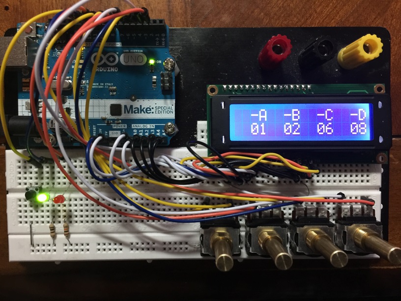
Decide if you can "live with" each switch offering only 0-7 (0r "1" to "8")... lots of advantages. Or, if you "must" have 0-9, you might as well go to 0-15 (usually represented as 0,1,2,3...,8,9,A,B,C,D,E,F)

THEN how do you read four of them?

I'd probably use a multiplexing scheme. (Go Google.) You can do it in hardware with a fancy extra chip. Or in software with just your Arduino. For 0-7, you "need" 3 digital inputs to the Arduino (4 gives you 0-15)... per switch module, if you don't multiplex... but that's "all" you would need. (Use a Mega clone!) Really simple programming. If you multiplex, you need th ebasic 3 or 4, plus two more lines which will be outputs from the Arduino to read four switch modules. 3 outputs lets you read up to 8 switch modules.

Go for it! Have fun! Wtie up what you've done at the Arduino playground or in a blog, for the next person. (There are probably existing accounts out there already.)cc

As I said

it would be trivial to wire the correct combination in series through the switches

Whether that is a reasonable solution or not remains to be seen based on the OPs actual requirements, available hardware, budget and experience.

Too often replies here go off at a tangent, the most common one being "do not use delay(), use millis() for timing instead" when the stated requirement is fully met by the use of delay(). Often, of course, the requirements are not stated in full or are changed as the project progresses.

Before suggesting a more complicated solution I will await further information from the OP.

I can't tell from all the replies if you are wanting to use mult-position switches or rotary encoders or if it matters. The HTCL 2022 chip you suggested looks to be a Rotary "Decoder" so I stayed with that assumption. Out of curiosity I wired up four basic Quadrature rotary encoders with a 2x16 display, a push button and two LED's just to see if I could locate a suitable library and all of this would actually work with an UNO. I have attached a photo of the prototype showing a correct combination and a lit Green LED. This example uses all but pins 0,1 and 13. Basically dial in four numbers by rotating clockwise to increase the number or counter-clockwise to decrease the number. Then when the four numbers look right press the button. If they are the right 4-digit combination the green LED lights up and if not then the red LED lights up. Then the numbers reset to zero. I didn't use a schematic but will draw one if that would help. Any basic 3 pin quadrature rotary encoders should work. Just tie the common pins to ground. I think the ones I used were from CTS part# 288V232R161B2.

For reference, I used this encoder library from PaulStoffregen. GitHub - PaulStoffregen/Encoder: Quadrature Encoder Library for Arduino

Here is the code for the UNO if you want to try and build something like this and play around with it or expand on it.

/* Basic 4 rotary encoder combination lock */

#define RedLED 10
#define GrnLED 11
#define Button 12

#define DigitMaximum 99

#include <Encoder.h>
#include <LiquidCrystal.h>

// initialize the display library with the numbers of the interface pins
LiquidCrystal lcd(14, 15, 16, 17, 18, 19);  //Display on Analog Pins 14-19

// define an array of four encoders
Encoder RotaryEncoder[4] = {
  Encoder(9, 8),               //Rotary Encoder 1 on pins 9 and 8
  Encoder(7, 6),               //Rotary Encoder 2 on pins 7 and 6
  Encoder(5, 4),               //Rotary Encoder 3 on pins 5 and 4
  Encoder(3, 2)                //Rotary Encoder 4 on pins 3 and 2
};

int Combination[4] = {1, 2, 6, 8}; //Define 4 digit combination here

int oldPosition[4] = {1, 1, 1, 1}; //Start with 1's to allow initial display

void setup() {
  pinMode(RedLED, OUTPUT);
  pinMode(GrnLED, OUTPUT);
  pinMode(Button, INPUT_PULLUP);
  Serial.begin(9600);
  Serial.println("Basic Encoder Test:");
  lcd.begin(16, 2);
  lcd.print("  -A  -B  -C  -D");
}

void loop() {

  int newPosition;
  char numbers[17];
  bool changeFlag = 0;

  for (int i = 0; i < 4; ++i) {
    newPosition = RotaryEncoder[i].read();
    if (newPosition >= 0 && newPosition <= DigitMaximum && (newPosition != oldPosition[i])) {
      oldPosition[i] = newPosition;
      changeFlag = 1;
    }
  }

  //Read button and test combination if pressed
  if (digitalRead(Button) == LOW) {
    bool CorrectCombination = 1;
    for (int i = 0; i < 4; ++i) {
      if (oldPosition[i] != Combination[i]) CorrectCombination = 0;
    }
    if (CorrectCombination) {
      digitalWrite(GrnLED, HIGH);   //Show Green if correct
      Serial.println("Correct Combination");
    } else {
      digitalWrite(RedLED, HIGH);   //Show Red if incorrect
      Serial.println("Incorrrect Combination");
    }
    delay(2000);
    while (digitalRead(Button) == LOW) {};         //Wait for button release
    digitalWrite(GrnLED, LOW);                     //Turn off LED's
    digitalWrite(RedLED, LOW);
    for (int i = 0; i < 4; ++i) {                  //Reset numbers to zero
      RotaryEncoder[i].write(0);
      oldPosition[i] = 0;
    }
    changeFlag = 1;
  }
  if (changeFlag) {   //Show new numbers if changed
    sprintf(numbers, "  %02d  %02d  %02d  %02d", oldPosition[0], oldPosition[1], oldPosition[2], oldPosition[3]);
    Serial.println(numbers);
    lcd.setCursor(0, 1);
    lcd.print(numbers);
    changeFlag = 0;
  }
  delay(10);
}

UKHeliBob:
Before suggesting a more complicated solution I will await further information from the OP.

I often wish for that. Sometimes it's like pulling teeth though...