Two problems same theme.
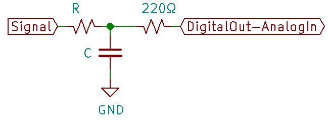
I have a circuit which reads an RC Voltage level via the A to D input, but I want to recharge the cap when the Voltage level drops below a set point.
Can I drive the A/D input high for a short time without configuring it as an output.
Second is a bit banged I2C communication where the digital lines are pulled high for communication with other devices.
Do I flip the digital pin to an output then pull low, or can I just write a low to that pin for correct I2C operation to take place.
Not directly. You should use a FET and a separate output pin to switch the FET on/off.
Switching the A/D input to output creates the possibility of discharging the capacitor through the CMOS driver. This thus means you must carefully construct your external circuitry. It is possible but if you must ask, you should not attempt.
In the first instance it is an A/D input which uses an RC as a time derived input
In the second instance, it is an I2C device which is not using the I2C I/O of any particular Arduino, just data pins.
All devices on an I2C network are configured as inputs with the lines tied high.
This is so that proper communication can be established and where more than one device can grab the line at any point in time.
This is done on many different MPU's including a PIC and Seimens devices I am interfacing with.
Interesting, I shall have a read up on that, thanks, although the Arduino manual does state that changing over from A/D to digital can be done at any point. Just wondered if anyone had done this
The question was , whether to do a write to an A/D pin, whilst still configured as an A/D pin or not, which you have answered.
Thanks
In the case of I2C the default HIGH state is not usually provided by the I/O pins themselves but is handled by using pull up resistors. These are typically high value( 10-50k ohm) tied from the i2c line to vcc.
since they are high ohms the I/O pins can easily overpower them when driven LOW.
But the writer was contemplating the A/D pin was not connected to external power sources. You are going from high-impedance to potentially the ground rail...
Magic Smoke is possible depending on what voltage/current can be sourced. Again, one could design around this but one must be aware of the ramification of what the internal output CMOS drivers create.
The I2C bus must have pull-up resistors, one on the SDA line and one on the SCL line. They're typically 4.7K or 10K ohm, but should be in the range of 2K to 10K.
Yes, on an AVR, using digitalWrite() while a pin is configured as input will enable or disable the internal 20-50K pullup resistor.
For faster charging (see post#9), you could use a current limiting resistor and temporarily configure the pin as an output to quickly charge or discharge the capacitor.
On an AVR, if the pin is externally pulled HIGH and is configured as INPUT, then you could just use pinMode() to "pulse" the pin LOW:
pinMode(pin, OUTPUT)    // pin is driven LOW
delayMicroseconds(us);  // duration for pin driven LOW
pinMode(pin, INPUT)     // pin is externally pulled HIGH
It all depends on the number of devices on the BUS and the PSU Voltage, I usually like to move away from too high a value given that a weak pullup is not very good on extended line lengths, where noise could be an issue.
I tend to use 6K8 pullups on a 5V supply when there are just 2 devices communicating.