Hello , i m going to do a project of inteligent house , i need to control color of all rgb leds at once so i try to use 2n3904 , but i need to be able to swich every light(led) separately so i try to use common anode rgb to be switched on/off by arduino . Also i want to limit current going from arduino , becouse i will be conecting another 20 leds .
Heres the schematic
JP 1 is external 5V supply
JP 2 to 4 are arduino PWM ouputs.
JP 5 to 10 are arduinos digital outputs .
Your image does not show for us (but it may for you.) That usually means that the permission is set to private, or that it is password protected. When I go to the image's url, I get a 403 error - no permission.
OK, that diagram is complete rubbish - and posted at too low a resolution as well.
You need to explain a whole lot more. What exactly do you wish to do? Are you proposing to mix colours using PWM? How many colours - R - G - B - do you propose to enable at once? It looks as if you are using the 2N3904s to implement colours and some other device which you have not specified to enable particular RGB LEDs.
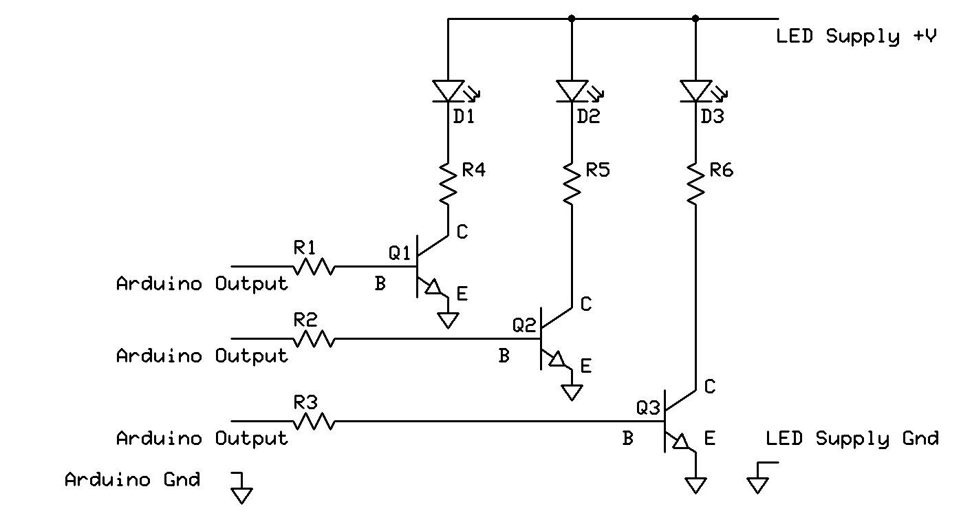
That is probably OK, but you have wired the transistors wrong with collectors going to 5 V when you are actually wanting to pull down the cathodes to ground - negative. A 2N3904 is rated for 200 mA absolute maximum; if driving a lot of LEDs you want something far better; a logic level power FET.
And why would you put a resistor in series with the LED anodes as well as the cathodes? That would not only seriously limit the current driving them which is important if they are used to light up something rather than just serve as indicators, but also mean the brightness of each will change depending on how many of the three are powered at any one moment.
What exactly are these LEDs? 300 Ohms suggests at most 10 mA - looks pretty but what do you expect it to light up in an "intelligent house"? If you really mean actual luminaires, they will require more like 350 mA at 12 V and you need a whole different circuit.
JP1 should be Ground (not +5)
It's the Emitters should go to JP1 and the Collectors to the LED cathodes (not what your circuit shows).
And eliminate R19-24, they are not needed.
Ok , thanks for feedback , let me explain better. I want to be able to change color of all 6 leds at once from warm(yeloworbrown) to cold(white) and back to warm , in a day cycle morning light is warm at linch light is cold and in the susnet warm . But i want to be able to switch all leds on/off Independently of each other . I will use buttons for switching . When the button is pressed it will send signal to arduino , also i want to do that with ir remote and maybe by m obile . Leds should not draw more the 15mA .
Andrejko778:
Hello , i m going to do a project of inteligent house , i need to control color of all rgb leds at once so i try to use 2n3904 , but i need to be able to swich every light(led) separately so i try to use common anode rgb to be switched on/off by arduino . Also i want to limit current going from arduino , becouse i will be conecting another 20 leds .
Heres the schematic
JP 1 is external 5V supply
JP 2 to 4 are arduino PWM ouputs.
JP 5 to 10 are arduinos digital outputs .
Firstly you have both per-LED and shared resistors for each group of LEDs - that's just going to
cause problems with the
brightnesses interfering depending on how many of the 3 are active. Just have resistors on one side of the
LEDs only. If you are intending to select one of J2/J3/J4 at a time, the resistors per LED are unneeded,
lose them and increase the values of the J5/6/7/8/9/10 resistors appropriately.
You should be using PNP switching transistors driven by J2/3/4, switching transistors use
common-emitter configuration. The transistors should be rated for enough current. Set the
base resistors so that the base current is about 5 to 10% of the total max load current.
2N2906 or 2N2907 are possible devices supporting upto half an amp or so.
Alternatively logic-level p-channel MOSFETs could be used.
With p-type devices the drive for J2/3/4 will be reversed in sense, LOW meaning ON
The emitter-follower configuration you have proposed will run the transistors very hot, probably
won't turn on the LEDs consistently, and the resistor values will need to be found by trial and error
to match the large voltage loss caused by the emitter-followers. Change to common-emitter!