Using a geometric series to control many LEDs

I think this question may be as much a mathematical question as it is an Arduino programming question.

I’m using a Leonardo and have the need to report several hundred data points using optocouplers. Rather than using a single optocoupler per data point, I realized that I could do this using 11 otptocouplers along with a “digital-code” and thereby be able to report up to 1024 unique conditions.

Here is the layout:

The 11 LEDs: A, B, C, D, E, F, G, H, I, J, K

These correspond to the following numbers:

image

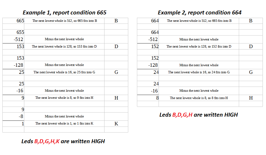
As an example, let’s say that the number 665 represented a condition that needed to be reported. So to report condition 665, the LEDs of optocouplers B,D,G,H,K would be written HIGH, and the remaining optocouplers LEDs would be written LOW. Here are a couple of examples showing how this works:

Unfortunately, my math skills have been under-used for a couple of decades. Is there an equation, whereby given the input of 665, the derivation of the corresponding LEDs could be calculated automatically? I’ve been looking at geometric series, but thus far the equations I have found don’t seem to be relevant for this objective. While the 1,2,4,8,16 etc is a geometric series, I’m not sure what the objective outlined above would be called.

From an Arduino code perspective, how would a function be designed so that the desired HIGH/LOW state of the 11 optocouplers LEDs could be passed to the function?

Project Note: Optocouplers have to be used because the circuit of the Arduino used for monitoring and the circuit of the other equipment must be kept separate. Serial communication is not an option.

Sure. Does it have to pretty? If not, you can just test of the number is bigger than 1024, if so, subtract 1024, then check if it's bigger than 512, if so, subtract 512, etc. Basically recursively subtracting your numbers from large to small until your remainder ends up 0.
Notice that you can conveniently express your number series as 2^N (which is why you smartly picked those numbers anyway!)

Use bits inside an int.

Assigning the value will automatically set the bits, that can be tested and pushed to the optos.

That's far smarter & faster than my silly approach.

@anon35827816 I was trying to work it out on paper, but it was getting so cluttered, I couldn’t make any real progress.

@Whandall thanks for the suggestion. I am totally out of my depth on this. Would it be possible to give an example of how this is done?

Congratulations! You have invented BINARY.

An easy way to convert a number to a set of pins being HIGH:

// List the pins, low bit (1) to high bit (1024)
const byte OutputPins[11] = {2, 3, 4, 5, 6, 7, 8, 9, 10, 11, 12}; // Can be in any order

void setup()
{
  for (int i = 0; i < 11; i++)
    pinMode(OutputPins[i], OUTPUT);
}

void SetOutputs(int value)
{
  for (int i = 0; i < 11; i++)
    digitalWrite(OutputPins[i], (value & (1 << i)) ? HIGH : LOW);
}

void loop()
{
  for (int i = 0; i < 2048; i++)
  {
    SetOutputs(i);
    delay(100);
  }
}
1 Like

@johnwasser already gave you an example.

@johnwasser I did have a bit of a sense of accomplishment on realizing that it could be done with 11 LEDS :wink: Those years of algebra and calculus finally paid off!

Thanks so much for the code solution... After hours of trying to figure this out on paper, I am really grateful.

Glad you like it. It's really easy... with decades of practice. :slight_smile:

11 outputs give 2048 (2 ^ 11) combinations.

If you split the value in two bytes, you can assign the first byte directly to PORTD 0...7 and the second to PORTB 4-5:

void set_outputs (int value)
  {
  PORTD = value&255;
  PORTB &= ~((value>>8)<<4);
  PORTB |= (value>>8)<<4;
  }

Connect LEDs to B5, B4, D7, D6, D5, D4, D3, D2, D1, D0 (for 1024 conditions from 0 to 1023 you need only 10 outputs).

(From a Direct Message)

The "(1 << i)" means 1 shifted left by 'i' bits. That gets you a 1, 2, 4, 8, 16, 32...

The "(value & (1 << i))" means, using the results of "(1 << i)" as a bit mask, return 0 if that bit of the value is 0 and non-zero if that bit of the value is a 1.

The "boolean ? true_value : false_value" is call a Ternary Operator. If the value to the left of the '?' is non-zero (true) use the true_value. If the value to the left of the '?' is 0 (false) use the false_value. In most cases this part is not really necessary: any 0 value is LOW and any non-0 value is HIGH, but there are a couple models where the names LOW and HIGH are special.

Very similar way: a list of pin numbers and a moving mask. Start with an integer containing zero. In a loop that goes through the pins from low bit to high bit, if the pin at that place in the array is reading LOW, add (or OR) the mask (1 << i) to the value. When the loop is done you have an integer.

It looks OK to me. Can you show the Serial Monitor output on the receive side?

@johnwasser Here’s the serial monitor showing the data coming in to the receive end. The only problem encountered is when receiving a single digit 1-9.

This problem can be corrected by sending 01, 02, 03, etc. Is there a way to correct for this in the Arduino code?

The decimal values shown (13, 23, 33) match the binary shown so the problem may be on the sending side. Do you show the binary patterns on the sending side before you send them?

If you don't connect the input pins they will read HIGH (because: INPUT_PULLUP) and show as 0. If you connect a pin to Ground it will read LOW and show as a 1. As you ground single pins from Pin 2 to Pin 7 do the values show up with a single 1 in the right place? If so, that shows the RECEIVE side is working as expected.

1 Like

I haven't set it up for this functionality, but I connected regular LEDs to the pins on the send side (in place of the optocouplers) and the problem persisted (1 would produce the 1101 pattern on the LEDs).

Yes, the values show up correctly.

I took a more closer look at the code on the send side and made the following change -- see the comment // <--ADDED THIS LINE HERE

The code in recvWithStartEndMarkers() is from Robin2's post on serial communication. I had originally commented this line out and then removed it completely. Restoring it as shown in Robin2's original code solved the problem. Now when 1 is sent, 1 is also received on the receiving side.

I have looked into the meaning of '\0' in the past and have revisited it again just now. I'm not sure why receivedChars[ndx] = '\0' would resolve the problem, and it would be interesting to learn why it works.

const byte OutputPins[6] = {2, 3, 4, 5, 6, 7};
//index is..................0, 1, 2, 3, 4, 5

String SerialMessageForCode;
const byte numChars = 4;
char receivedChars[numChars];
boolean newData = false;

void setup() {
  for (int i = 0; i <= 5; i++) pinMode(OutputPins[i], OUTPUT);
  Serial.begin(9600);
}

void SetOutputs(int value) { 
  for (int i = 0; i <= 5; i++)
    digitalWrite(OutputPins[i], (value & (1 << i)) ? HIGH : LOW);
} 

void loop() {
    recvWithStartEndMarkers(); //Receive data enclosed in <>  i.e.,  <Message>
    sendData(); //Send data by optoisolator to other Leonardo
}

void recvWithStartEndMarkers() {
    static boolean recvInProgress = false;
    static byte ndx = 0;
    char startMarker = '<';
    char endMarker = '>';
    char rc;
 
    while (Serial.available() > 0 && newData == false) {
        rc = Serial.read();

        if (recvInProgress == true) {
            if (rc != endMarker) {
                receivedChars[ndx] = rc;
                ndx++;
                if (ndx >= numChars) {
                    ndx = numChars - 1;
                }
            }
            else {
                receivedChars[ndx] = '\0'  // <--ADDED THIS LINE HERE
                recvInProgress = false;
                ndx = 0;
                newData = true;
            }
        }
        else if (rc == startMarker) {
            recvInProgress = true;
        }
    }
}

void sendData() {
    if (newData == true) {
    newData = false;
    SetOutputs(atoi(receivedChars));
    delay(2000);
  }
}

If you don't put an "end of string" marker ('\0') in your buffer, the string in the buffer continues until it reaches a \0. If you send "1234" followed by "AB" the buffer will contain the string "AB34".

I get it now; that makes sense.

Thanks @johnwasser and everyone for your help with this thread!

This topic was automatically closed 180 days after the last reply. New replies are no longer allowed.