I am trying to get and WINSTAR OLED working together with a microSD card. I have test each parts separately and they work. But in combined together the OLED doesn't work I get the following error "OLED not found".
This is how I have wired the OLED and SD card to the UNO.
SD card wiring
MISO direct to D12 (Uno)
MOSI through 3.3V level shifter to D11
SCK through 3.3V level shifter to D13
CS through 3.3V level shifter to D10
OLED wiring
SCL - A5
SDA - A4
Below is my test code.
#include <Wire.h>
#include <Adafruit_GFX.h>
#include <Adafruit_SSD1306.h>
#include <SD.h>


// --- OLED Setup ---
#define SCREEN_WIDTH 128
#define SCREEN_HEIGHT 64
#define OLED_RESET     -1
Adafruit_SSD1306 display(SCREEN_WIDTH, SCREEN_HEIGHT, &Wire, OLED_RESET);

// --- SD Card ---
const int sdCardCS = 10; // Chip Select pin for SD card

void setup() {
  Serial.begin(9600);
  delay(1000); // Give some time after reset

  // Deactivate SD before initializing OLED
  pinMode(10, OUTPUT);
  digitalWrite(10, HIGH);

  // --- Initialize OLED ---
  if (!display.begin(SSD1306_SWITCHCAPVCC, 0x3C)) {
    Serial.println(F("OLED not found"));
    while (true); // Stop here if OLED fails
  }
  display.clearDisplay();
  display.setTextSize(1);
  display.setTextColor(SSD1306_WHITE);
  display.setCursor(0, 0);
  display.println("OLED OK");
  display.display();
  Serial.println("OLED initialized successfully");

  delay(1000); // Short delay to show OLED message

  // --- Initialize SD Card ---
  if (!SD.begin(sdCardCS)) {
    Serial.println("SD card init failed");
    display.setCursor(0, 16);
    display.println("SD Failed");
    display.display();
  } else {
    Serial.println("SD card initialized");
    display.setCursor(0, 16);
    display.println("SD OK");

    // Write test data
    File testFile = SD.open("test.txt", FILE_WRITE);
    if (testFile) {
      testFile.println("Test from Arduino");
      testFile.close();
      Serial.println("Wrote to SD");
      display.setCursor(0, 32);
      display.println("SD Write OK");
    } else {
      Serial.println("Write failed");
      display.setCursor(0, 32);
      display.println("SD Write FAIL");
    }

    display.display();
  }
}

void loop() {
  // Nothing here for now
}
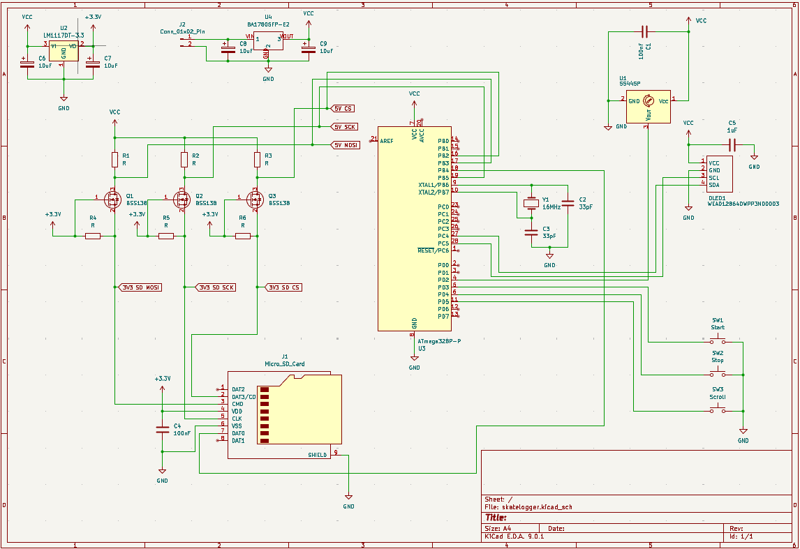
That sounds like a hardware problem, they are on different buses. What value of pull up resistors did you use. What does the scanner show? Posting an annotated schematic would help.
Nice schematic, you do good work. The only problem I believe is there is you do not have pull up resistors on the I2C lines PC4(27) and PC5(28). Add 4.7K resistors from each of these pins to +5V. I will also recommend adding some high frequency bypass capacitors at the in and out of each regulator and each of the connectors.
After you add the resistors run the I2C scanner program and be sure it gives you the same port as you are using in your code.
Sketch uses 22340 bytes (69%) of program storage space. Maximum is 32256 bytes.
Global variables use 1324 bytes (64%) of dynamic memory, leaving 724 bytes for local variables. Maximum is 2048 bytes.
The Adafruit_SSD1306 library needs to allocate 1024 bytes of ram (dynamic memory) at run-time for a display buffer, you only have 724 bytes available.
It's not the problem, but for future reference, the level shifters you are using are bidirectional, but the three SPI lines are unidirectional. So you could just use a diode and a pullup resistor.
Thanks for the comment about the schematic , I will and the 4K7 pull up resistors to the I2C line as mentioned. Not to sure what you mean about the I2C scanner program.
I think it's in the examples->Wire menu. It scans every possible address on the i2c bus to see if any device answers, and displays the results on serial monitor. A very useful tool to run any time you add a new i2c device to your circuit.