I am currently working on documentation part and project that I integrated TMC2209 is also on hold. I hope it will be super useful for others with all features explained in simple manner and examples.
Thanks @kyle_stenersen for your response!
Hi guys,

TL;DR:
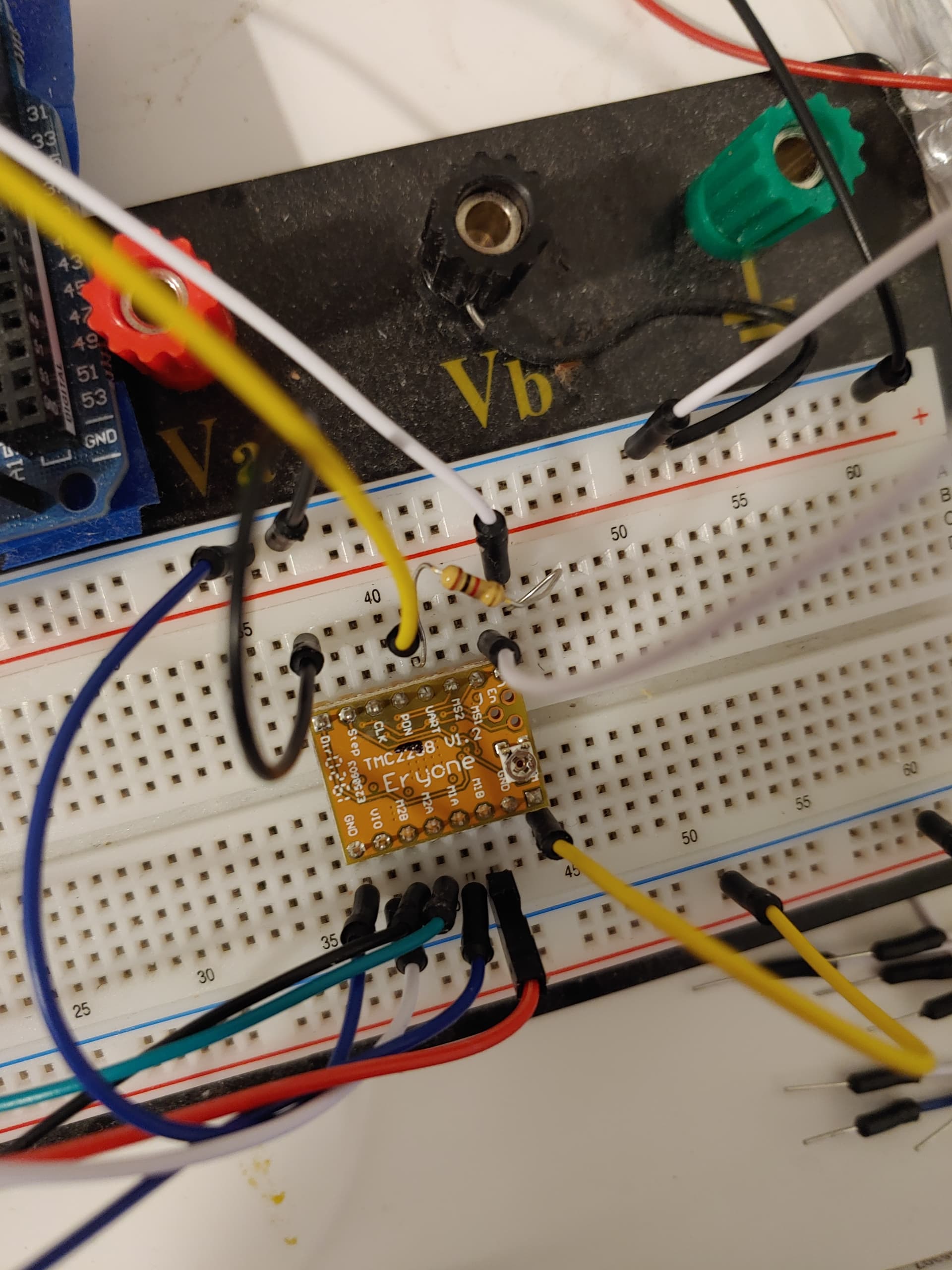
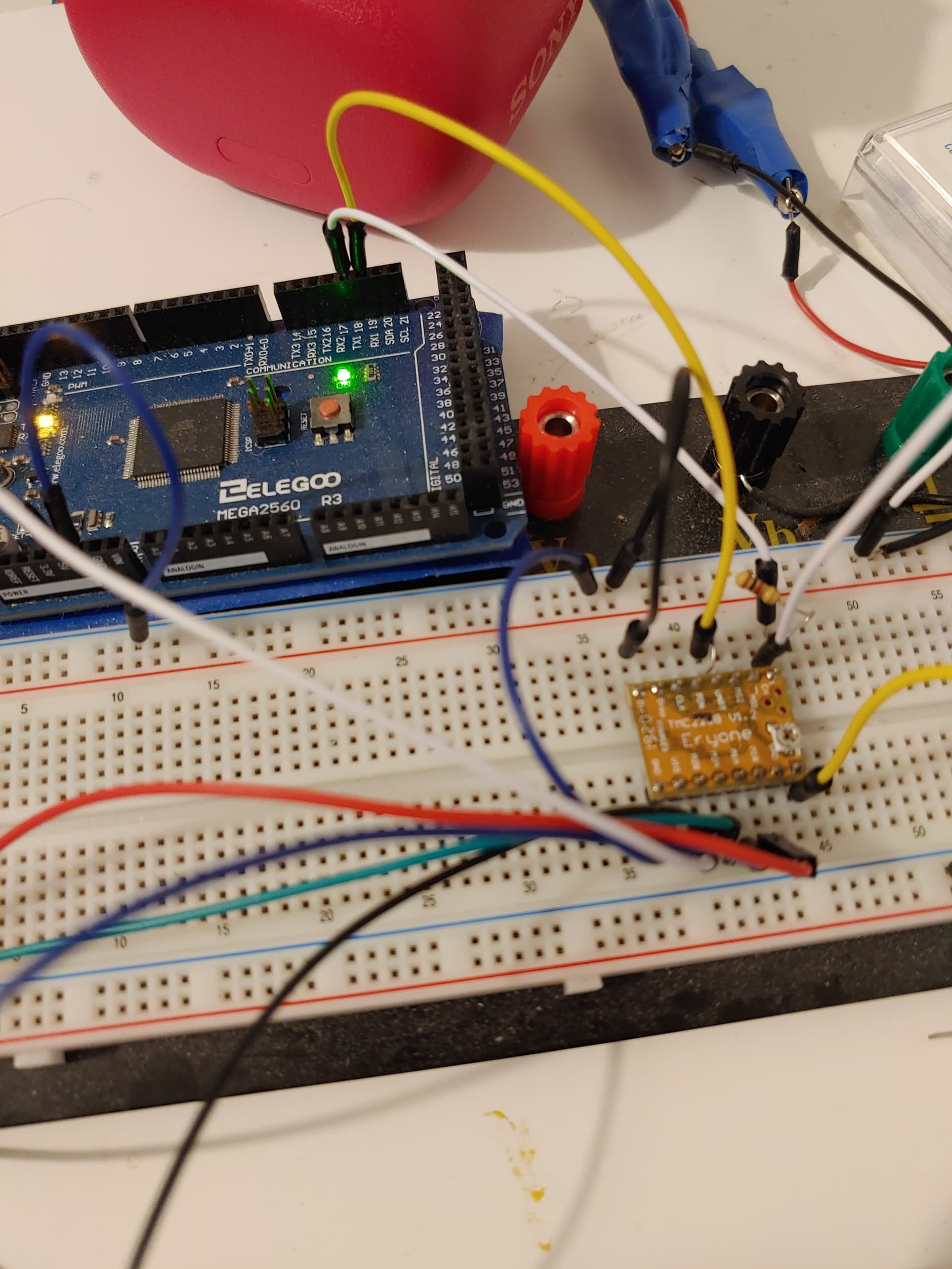
- Modify the SilentStepperStick with the solder-blob (see picture)
- Make sure there's a 10k resistor between RX and TX signal from your MCU and connect both to UART pin of the SilentStepperStick.
- Use a known working example code. I recommend the one by @monkeyfist.
- Optionally connect with Watterott Configurator.
This post has been extremely useful. I am currently also working on a project with three TMC2209 SilentStepperModules.
The least I could do, is take some pictures of the solder-blob modification that is needed to get UART running.
I used a modified version of @monkeyfist's sketch from this post. What also helped me, was to connect the Watterott Configurator with a RS232 TTL to USB Converter. After that connection has been established, I was sure, that the hardware basically works.
1 Like
@ceerious Wonderful connection technique using solder-blob!
I had to revisit this problem, and had a hard time getting it working again.
For reference for others, here is the code and wiring that I was able to get working to use the serial interface with the tmc2208. That's 2208, not 2209.
You have to solder the jumper pads as I described above.
DO NOT disconnect things while the 12 volts power supply is turned on, I fried one board by accident like that. Disconnecting the stepper while things are turned on will also fry the board.

code simplified
#include <TMCStepper.h>

#define SERIAL_PORT Serial1 // HardwareSerial port
#define DRIVER_ADDRESS 0b00 // TMC2209 Driver address according to MS1 and MS2

#define R_SENSE 0.11f // Match to your driver
                      // SilentStepStick series use 0.11
                      // UltiMachine Einsy and Archim2 boards use 0.2
                      // Panucatt BSD2660 uses 0.1
                      // Watterott TMC5160 uses 0.075

bool shaft = false;  // ONLY NEEDED FOR CHANGING DIRECTION VIA UART, NO NEED FOR DIR PIN FOR THIS

TMC2208Stepper driver(&SERIAL_PORT, R_SENSE);
int accel = 0;

void setup() {
SERIAL_PORT.begin(115200);      // INITIALIZE UART to TMC2208
Serial.begin(115200);
delay(500);
Serial.println(F("Serial Initialized"));

  driver.begin();                // Initialize driver

  driver.toff(5);                 // Enables driver in software

  driver.rms_current(600);       // Set motor RMS current
  Serial.print("current set to:");
  Serial.println(driver.rms_current());

  driver.microsteps(256);           // Set microsteps to 1/2

  driver.pwm_autoscale(true);   // Needed for stealthChop
  driver.en_spreadCycle(true);   // Toggle spreadCycle for smooth & silent operation

}

void loop() {

uint16_t msread=driver.microsteps();
Serial.print(F("Read microsteps via UART to test UART receive : "));
Serial.println(msread);


driver.rms_current(600);


//Serial.println(F("Wait 3sec and turn current low so you can turn the motor shaft"));
//driver.rms_current(10);
//delay(3000);
Serial.println("move under tmc2208 uart interface control");
//driver.TPWMTHRS(47);//transition threshold from one pwm mode to the other one, stealthchop to spreadcyccle I think, in clock periods per 1/256 microstep, the internal clock is 12 mhz

accel=500;
Serial.print("accel:");
Serial.println(accel);
long int spd = 102400;
Serial.print("spd:");
Serial.println(spd);
for (long int i = 0; i <=spd; i = i + accel){
driver.VACTUAL(i); //SET SPEED OF MOTOR
Serial.print("vactual set to:");
Serial.println(driver.VACTUAL());
delay(100);

}

for (long int i = spd; i >=0; i = i - accel){
driver.VACTUAL(i); //SET SPEED OF MOTOR
Serial.print("deccelerating, vactual set to:");
Serial.println(driver.VACTUAL());
delay(100);

}

shaft = !shaft; // REVERSE DIRECTION
driver.shaft(shaft); // SET DIRECTION

}
They sell these drivers in UART & "DIY" STEP/DIR configurations. The ones sold as UART will come with the UART jumper pre soldered. So just save yourself the trouble and buy the UART configured drivers.
I've been reading this topic and it was a great help. Special thanks to adouglas88 for the code. And AnshumanFauzdar, I'm looking forward to your documentation.
I posted my personal result from this topic in a new thread: TMCstepper - Arduino - TMC2209
@AnshumanFauzdar hi, i am working on similar project, it would be good if you can share starter guide for TMC2209.
i am using MKS gen 1.4 Board with TMC2209
my code is working fine with DRV8825 however i would like replace with TMC2209 considering its advantages, mainly coolsteps and uart communications.
my main doubts are
- MKS board pins for UART as all pins are pre assigned as per pin maping
- is 4 drivers with same address may not create an issue? or we can change the address?
apart from this is there anyway to use this driver in UART mode with arduino uno and cnc shield v3 as Arduino Uno have only one serial port and with #softwareserial its not getting compiled.
really appreciate effort puts by you and other user as well, and thanks in advance. please help me out in this.
Regards KD
1 Like
@Kdekivadiya I have already started writing starter guide and might be ready in coming weeks.
1 Like
@AnshumanFauzdar Any chance that starter guide made it?
@spokes not yet, busy in some other projects.
Thanks to the example by @monkeyfist I have a working UART, but I'm confused on how to force the motor to use X amount of current from my 12v supply. I'm not sure why the final current is lower than whatever I pass to rms_current(), but it always is. I was hoping that no matter what coasting speed or ramp speed I'm using, 900ma is always used.
According to TMCStepper.cpp:
 void TMCStepper::rms_current(uint16_t mA) {
   uint8_t CS = 32.0*1.41421*mA/1000.0*(Rsense+0.02)/0.325 - 1;
   // If Current Scale is too low, turn on high sensitivity R_sense and calculate again
   if (CS < 16) {
     vsense(true);
     CS = 32.0*1.41421*mA/1000.0*(Rsense+0.02)/0.180 - 1;
   } else { // If CS >= 16, turn off high_sense_r
     vsense(false);
   }

   if (CS > 31)
     CS = 31;

   irun(CS);
   ihold(CS*holdMultiplier);
   //val_mA = mA;
 }
(I have both irun and ihold set to 31... max/100%)
FWIF, there's a serious difference between using rms_current(939) and rms_current(940) because when vsense is true (ie CS > 16), .18 is used, otherwise when false .32 is used (as explained on p.51 of datasheet).
Regardless, the current drawn isn't 939ma or 940ma, but much lower. It is~132ma when I use rms_current(939) and ~390ma when rms_current(940), the difference of 1 and over double the current.
The datasheet does mention: "For high precision motor operation, work with a current scaling factor in the range 16 to 31...", but I'm not sure why TMCStepper makes this distinction within the rms_current() even when I have irun and ihold set to 31 (seems like .32 should be used if irun = 31... 31 is also default I believe).
I'm brand new to all of this, so sorry if the answer is obvious.
Use this to read the current:
Serial.println(driver.cs2rms(driver.cs_actual()),DEC);
It does the conversion automatically using the library.
Should have included it in my example.
driver.rms_current(940); // in setup()
driver.irun(31);
// in loop()
Serial.println(driver.cs2rms(driver.cs_actual()),DEC); // 1767
Serial.println(driver.cs_actual()); //31
I'm brand new to all of this so maybe my bench supply isn't supposed to match the value I pass in. My bench supply reads ~395ma and the stepper motor doesn't get warm.
The conversion of what? If you mean that evaluation, yes, and it doesn't seem like it will ever evaluate to the expected user value. It must evaluate for a reason right? Without editing TMCStepper itself, I'm not sure if I can ever read 900 off of my bench supply since it caps CS at 31.
Again, I'm new ![]()
You bench supply wont show the same currents, stepper motors work differently. This is something i have been trying to wrap my head around lately. As i also first though that it would draw the current i'm setting in the driver.
The reported current is correct, its the current the stepper is operating at. But i think it changes the voltage, so it actually draws less current from the power source.
You can google posts about this:
"You need to be looking at power, not current. You will never be drawing full motor current, at full supply voltage. The motor is rated at 4.17V, 2.8A. Power is voltage times current, so the max motor power is 4.17 x 2.8 = 11.7W. your power supply is 36V, and you're measuring 0.5A, so the power is 36 * 0.5 = 18W. "
"The conversion of what?"
The conversion of cs_actual readout to amps.
Also, your use of irun is incorrect. It overrides your current setting. You can just remover irun. IRUN sets the rms_current, rms_current is just the same with amps so its easier to set.
This is why you get higher amp reading on the serial readout than you have set. As you are setting your amps at max (~1720ma) via irun(31).
irun = 31 and with rsense of 0.11, the current is 1700mA. So just use rms_current, less confusing.
I'm confused ![]() You mean if the divisor is .32 correct?... or should it be 1700 all the time?
You mean if the divisor is .32 correct?... or should it be 1700 all the time?
driver.rms_current(939) sets vsense(true) so the divisor becomes .18 but, cs_actual is 31 still. In this case, driver.cs2rms(driver.cs_actual()) returns 979, not 1767. Any value < 940 passed to rms_current() chooses the .18 divisor, and value >= 940 chooses .32, which is when 1767 is seen and cs_actual is still 31. cs_actual is always 31 in either case.
Also, if the motor internally changes the voltage, that's fine, but it's still not pulling 900ma @ 12v (10.8w). I wouldn't care if it changes it to 1200v @ 9ma, as long as it does. However, when my bench supply reads 12v @ 400ma, there's no way it's the desired 10.8 watts inside that motor.
You are confusing yourself. Dont use IRUN at all, just use the rms_current to set the current. Thats simple.
ok.
@spokes
I now think that the bench power supply wont show the total current, because its too slow to react. That the only way to see the actual current draw would be to use an oscilloscope.
"If you want to measure current from power source like battery / power supply connect ammeter in series and measure. But it will be fluctuating as motor rotates. A digital storage oscilloscope with current probe is the appropriate one to measure fluctuating current. If the current in one conductor ( out of four) is to be measured connect current probe in that line and record. An ammeter may not give correct value as current is fluctuating."
The current that the TMC driver reports is correct, its just chopped so fast that your bench supply's meter cant react to it.
I'm sure you're right, it's just a little deceiving.
How do you use 2+ steppers in UART? I tried using SERIAL1 along with SERIAL2 and although it partially works, the microsteps only set for UART1when I use UART1 alone... without UART2.
UART2: per your example just works.
UART1: works, but I have to use ESP.restart() to have the steps set.
UART1 & UART2: microsteps never set for the UART1 connection... but after ESP.restart() they do set for UART2. Also, TMC drivers have to be powered down to flash.
In all cases driver.current() seems to always work.
Lastly and oddly, I have a function to move a motor 1 full rotation in 2 seconds. If using UART1 & UART2... after reset() the X motor moves at 4x LESS steps (only 90 degrees in 2 seconds). and the Z motor moves 4x MORE setps (1440 degrees in 2 seconds). The code looks right, but I must be missing something.
#include <Arduino.h>
#include <TMCStepper.h>
#include "FastAccelStepper.h"

#define SERIAL_PORT_Z Serial1 // HardwareSerial port pins 9 & 10
#define SERIAL_PORT_X Serial2 // HardwareSerial port pins 16 & 17
#define DRIVER_ADDRESS 0b00 // TMC2209 Driver address according to MS1 and MS2
#define R_SENSE 0.11f // Match to your driver
                      // SilentStepStick series use 0.11
                      // UltiMachine Einsy and Archim2 boards use 0.2
                      // Panucatt BSD2660 uses 0.1
                      // Watterott TMC5160 uses 0.075
TMC2209Stepper driver_x(&SERIAL_PORT_X, R_SENSE, DRIVER_ADDRESS);
TMC2209Stepper driver_z(&SERIAL_PORT_Z, R_SENSE, DRIVER_ADDRESS);

FastAccelStepperEngine engine = FastAccelStepperEngine();
#define DIR_PIN_X  14
#define STEP_PIN_X 12
FastAccelStepper *motor_x = NULL;
#define DIR_PIN_Z  26
#define STEP_PIN_Z 27
FastAccelStepper *motor_z = NULL;

void setup()
{
    Serial.begin(115200);
    SERIAL_PORT_X.begin(115200);
    SERIAL_PORT_Z.begin(115200);
    delay(1000);

    driver_x.begin();
    driver_z.begin();

    driver_x.toff(5);
    driver_x.rms_current(600); // NOTE: 600 initially
    driver_x.microsteps(16);   // NOTE: 16
    driver_x.pwm_autoscale(true);
    driver_x.en_spreadCycle(true);

    driver_z.toff(5);
    driver_z.rms_current(600);
    driver_z.microsteps(16);
    driver_z.pwm_autoscale(true);
    driver_z.en_spreadCycle(true);

    engine.init();

    motor_x = engine.stepperConnectToPin(STEP_PIN_X);
    motor_x->setDirectionPin(DIR_PIN_X);
    motor_x->setSpeedInHz(1600);
    motor_x->setAcceleration(5000);

    motor_z = engine.stepperConnectToPin(STEP_PIN_Z);
    motor_z->setDirectionPin(DIR_PIN_Z);
    motor_z->setSpeedInHz(1600);
    motor_z->setAcceleration(5000);
}
void move_ms8(FastAccelStepper* motor, TMC2209Stepper& driver) {
    // full rotation in 2 seconds... hopefully
    uint16_t ms = driver.microsteps();
    if (ms == 256) { ms = 8; }
    motor->setSpeedInHz(100 * ms);
    motor->move(200 * ms);
}
unsigned long last_ms = millis();
void loop()
{
    if (millis() - last_ms > 6000) {
        last_ms = millis();
        move_ms8(motor_x, driver_x);
        move_ms8(motor_z, driver_z);
        driver_x.rms_current(1000);// works fine, always sets properly
        driver_x.microsteps(32);   // requires ESP.restart() to set
        driver_z.rms_current(1000);// works fine
        driver_z.microsteps(32);   // NEVER sets
        Serial.printf("x rms_current: %d\n", driver_x.rms_current());
        Serial.printf("x microsteps:  %d\n", driver_x.microsteps());
        Serial.printf("z rms_current: %d\n", driver_z.rms_current());
        Serial.printf("z microsteps:  %d\n", driver_z.microsteps());
    }
    if (Serial.available()) {
        ESP.restart();
    }
}

// Prints before ESP.restart():
// x rms_current: 994
// x microsteps:  8
// z rms_current: 994
// z microsteps:  256
//
// After restart:
// x rms_current: 994
// x microsteps:  32
// z rms_current: 994
// z microsteps:  256