Using analogWrite and getting strange initial results

I have a sketch to control an RGB LED strip that fades in and out of several different states. Think night, sunrise, day, sunset and then night again. When i start the sketch or reset the Uno/Nano, after the initial settings are sent to the PWM pins (in the setup() function), the LEDs blink off before the main() starts executing.

Is this normal? I don't want it to happen.

// SIM Day Night Control Rel.3 ver.0


#define initRed 0
#define initGrn 0
#define initBlu 200

int prevRedPWM = initRed; // start with 6:00 AM values
int prevGrnPWM = initGrn;
int prevBluPWM = initBlu;

int RedPWMTarget, GrnPWMTarget, BluPWMTarget; // PWM variables
float diffRed, diffGrn, diffBlu;

int  iter, maxiter; // time/schedule variables
unsigned long fadeTime;
unsigned long currentTime, beginTime, loopBegin;

int RedOut = 11; // GPIO ouput pins in use (no input GPIO pins) 9,11,10
int GrnOut = 10;
int BluOut = 9;


//test bool readln_PWMColors(int& Value1, int& Value2, int& Value3);
bool doneRed = false, doneGrn = false, doneBlu = false; // status boolean variables

int RedPWM = initRed;
int GrnPWM = initGrn;
int BluPWM = initBlu;
const unsigned long   deltaSchedule = 5000ul;
const int indexMax = 10;
int simData [indexMax] [3] = {
  //  R  G  B

  { 0, 0, 200}, // night
  { 0, 0, 200},
  { 50, 0, 200},
  { 254, 84, 0}, // sunrise
  { 254, 84, 0},
  { 245, 245, 245}, // daylight
  { 245, 245, 245},
  { 245, 245, 245},
  { 152, 0, 217}, // sunset
  { 152, 0, 217}

};


// =======
//  setup
// =======

void setup() {
  Serial.begin(9600);
  fadeTime = (unsigned long) ((deltaSchedule / 256) - 1);
  maxiter = deltaSchedule / fadeTime;
  pinMode(RedOut, OUTPUT); // GPIO ouput pins in use (no input GPIO pins)
  pinMode(GrnOut, OUTPUT);
  pinMode(BluOut, OUTPUT);
  // Set up initial state
  analogWrite(RedOut, initRed); // output initial PWM values
  analogWrite(GrnOut, initGrn);
  analogWrite(BluOut, initBlu);


}


// ======
//  loop
// ======

void loop() {
  // Wait for color change command,,,
  //test### while ( !Serial.available());
  for (int index = 0; index < indexMax; index++) { //test

    // test### Get target PWM connands from test/sim array
    // Get target PWM values for LED colors from serial port.
    // test### readln_PWMColors(RedPWMTarget, GrnPWMTarget, BluPWMTarget);
    RedPWMTarget = simData [index][0]; //test###
    GrnPWMTarget = simData [index][1]; //test###
    BluPWMTarget = simData [index][2]; //test###

    // Calculate incremental differences to target PWM values
    diffRed = (float)(RedPWMTarget - prevRedPWM) / (float)maxiter; // Calculate PWM changes for Red fade
    diffGrn = (float)(GrnPWMTarget - prevGrnPWM) / (float)maxiter; // ditto for Green fade
    diffBlu = (float)(BluPWMTarget - prevBluPWM) / (float)maxiter; // ditto for Blue fade

    // initialize flags  (doneXxx)mand times (xxxxTime/xxxxBegin)
    doneRed = false; doneGrn = false; doneBlu = false; // set color output status
    beginTime = millis(); currentTime = millis(); loopBegin = millis(); iter = 1;

    //while elapsed time is less than the defined time for each loop
    while (currentTime - loopBegin <= deltaSchedule)
    {
      currentTime = millis();
      if (currentTime - beginTime >= fadeTime) { // fade from old to new PWM values in the current timeslice
        //                                          while elapsed time is less than the calculated fade time
        // Red PWM
        if (!doneRed) { // not done displaying Red
          RedPWM = (int)((float)prevRedPWM +  ((float)iter * diffRed)); // calculate next(?previous) PWM value
          if (abs(RedPWM - RedPWMTarget) <= 1) { // check for end of fade
            RedPWM = RedPWMTarget; // set PWM value = target
            doneRed = true;  // set flag indicating finished fading to target PWM value
          }
        }
        // Grn PWM
        if (!doneGrn) {
          GrnPWM = (int)((float)prevGrnPWM +  ((float)iter * diffGrn));
          if (abs(GrnPWM - GrnPWMTarget) <= 1) { // check for end of fade
            GrnPWM = GrnPWMTarget;
            doneGrn = true;
          }
        }
        // Blu PWM
        if (!doneBlu) {
          BluPWM = (int)((float)prevBluPWM +  ((float)iter * diffBlu));
          if (abs(BluPWM - BluPWMTarget) <= 1) { // check for end of fade
            BluPWM = BluPWMTarget;
            doneBlu = true;
          }
        }
        analogWrite(RedOut, RedPWM); // output intermediate/final PWM values
        analogWrite(GrnOut, GrnPWM);
        analogWrite(BluOut, BluPWM);
        iter++; // test###
        beginTime = millis(); // set beginning of next timeslice
      } // for fading time slice
    } // while in current scenario
    prevRedPWM = RedPWM;
    prevGrnPWM = GrnPWM;
    prevBluPWM = BluPWM;
  } // end fade command (while/for)
  RedPWM = 0; GrnPWM = 0; BluPWM = 0;
}

This will make LEDS blue.

#define initRed 0
#define initGrn 0
#define initBlu 200
. . .
  analogWrite(RedOut, initRed); // output initial PWM values
  analogWrite(GrnOut, initGrn);
  analogWrite(BluOut, initBlu);
  • Avoid while(. . .) unless the code section executes very quickly.
  • Look into how State Machines SM work, examples are found in the Tutorials forum.
    Use a SM for this.
  • Highly recommend you place one statement per line.
    It helps expose things as a sequence.
    i.e. It’s easier for volunteers to follow your code.

Yes, I know it will make the LEDs blue. That is what I wanted. But once they display blue, they turn off for a noticeable period of time before the next set of analogWtite commands is executed. I am looking for an explanation of this behavior.

The use of while is appropriate in this program, as it is used as a non-blocking timer for multitasking the fading of three LEDs in any combination of start and stop values.

I am very familiar with state machines (having been a professional programmer for over 50 years). There are too many discrete states to use a SM. Almost 17 million states.

I get your comment about one statement per line. But I only break this rule when initializing a set of variables with a common use so putting them all on one line adds to their understanding. For example,
RedPWM =0; GrnPWM=0; BluPWM=0;
There are only 7 lines with multiple statements out of 180, so I don’t see that as a problem. Particularly since I use the technique to highlight variables with similar function.

  • Looking forward to you helping us old guys in the future.
    We need helpers like you here.

  • Away from my Arduino so cannot test out the sketches actions just now.

1 Like
  • Using a Common Anode RGB LED
  • blink is not observed here.
  • At reset time the LEDs go almost a bright white colour, dim to light blue, dim to dim to white, brighten to maybe white green etc.
  • No blinking of LEDs just controlled dimming is seen.

EDIT

  • Just tried a Common Cathode.
  • Starts out as Blue, controlled dimming to: Pink then White then Yellow/Green then Whitish then light Blue then Pinkish, back to Blue repeating . . .
  • No blinking of LEDs just controlled dimming is seen.

Double check your wire connections.

Maybe if you set init state before pinMode to OUTPUT?

void setup() {
  Serial.begin(9600);
  fadeTime = (unsigned long) ((deltaSchedule / 256) - 1);
  maxiter = deltaSchedule / fadeTime;
  analogWrite(RedOut, initRed); // output initial PWM values
  analogWrite(GrnOut, initGrn);
  analogWrite(BluOut, initBlu);
  pinMode(RedOut, OUTPUT); // GPIO ouput pins in use (no input GPIO pins)
  pinMode(GrnOut, OUTPUT);
  pinMode(BluOut, OUTPUT);
  // Set up initial state


}

@JCA34F, changing the sequence will not help (at least on AVR based boards). analogWrite() does not need a separate pinMode(); from the source code

void analogWrite(uint8_t pin, int val)
{
    // We need to make sure the PWM output is enabled for those pins
    // that support it, as we turn it off when digitally reading or
    // writing with them.  Also, make sure the pin is in output mode
    // for consistenty with Wiring, which doesn't require a pinMode
    // call for the analog output pins.
    pinMode(pin, OUTPUT);

It was programmed for a common anode strip. But your description of the common cathode strip is closest to what I expect. ?

To all… the undesired blink occurs once after reset and the LEDs are blue. So what happens is reset, LEDs blue, LEDs off, LEDs blue and then fade through various colors. The LEDs off is undesirable

Your project in Wokwi simulation:

Is it common anode or common cathode ?

What you describe might be a reset. How many of which leds are you driving and what power supply do you use ? How is the grounding ?

A reset can be recognized by adding a Serial.println() in setup():

void setup() 
{
  Serial.begin(9600);
  Serial.println("The sketch has started");
  ...

But that only works if computer with the Serial Monitor is connected.

You could create a startup sequence.

  Serial.print("Test blinks... ");
  for(int b=255; b>0; b/=2)
  {
    analogWrite(RedOut, b);
    analogWrite(GrnOut, b);
    analogWrite(BluOut, b);
    delay(200);
    analogWrite(RedOut, 0);
    analogWrite(GrnOut, 0);
    analogWrite(BluOut, 0);
    delay(200);
  }
  Serial.println("Done");
  delay(1000);

@Koepel The LEDs are on a 50’ strip of RGB LEDs. And are driven through 2N7000 MOSFETs. They and the Nano run off a 2A 12V bench power supply. The combination draws from 170mA to 700mA. Note that the majority of the current drawn (for the LEDs) is NOT supplied by the Nano; it’s supplied by the 2N7000s.

I may use the println in setup trick. Although I can’t imagine why it would reset? It’s only drawing 350mA at that point.

Hi, @djsfantasi

What model Arduino are you using?

Thanks.. Tom.. :smiley: :+1: :coffee: :australia:

@TomGeorge
It’s an Arduino Nano

And suddenly!!! It’s working. I thought I was just cleaning up some whitespace but must’ve fixed something…

A current listing follows.

// SIM Day Night Control Rel.3 ver.0


#define initRed 0
#define initGrn 0
#define initBlu 200

int prevRedPWM = initRed; // start with 6:00 AM values
int prevGrnPWM = initGrn;
int prevBluPWM = initBlu;

int RedPWMTarget, GrnPWMTarget, BluPWMTarget; // PWM variables
float diffRed, diffGrn, diffBlu;

int  iter, maxiter; // time/schedule variables
unsigned long fadeTime;
unsigned long currentTime, beginTime, loopBegin;

int RedOut = 11; // GPIO ouput pins in use (no input GPIO pins) 9,11,10
int GrnOut = 10;
int BluOut = 9;


//test bool readln_PWMColors(int& Value1, int& Value2, int& Value3);
bool doneRed = false, doneGrn = false, doneBlu = false; // status boolean variables

int RedPWM = initRed;
int GrnPWM = initGrn;
int BluPWM = initBlu;
const unsigned long   deltaSchedule = 5000ul;
const int indexMax = 10;
int simData [indexMax] [3] = {
  //  R  G  B

  { 0, 0, 200}, // night
  { 0, 0, 200},
  { 50, 0, 200},
  { 254, 84, 0}, // sunrise
  { 254, 84, 0},
  { 245, 245, 245}, // daylight
  { 245, 245, 245},
  { 245, 245, 245},
  { 152, 0, 217}, // sunset
  { 152, 0, 217}

};


// =======
//  setup
// =======

void setup() {
  Serial.begin(9600);
  fadeTime = (unsigned long) ((deltaSchedule / 256) - 1);
  maxiter = deltaSchedule / fadeTime;
  pinMode(RedOut, OUTPUT); // GPIO ouput pins in use (no input GPIO pins)
  pinMode(GrnOut, OUTPUT);
  pinMode(BluOut, OUTPUT);
  // Set up initial state
  analogWrite(RedOut, initRed); // output initial PWM values
  analogWrite(GrnOut, initGrn);
  analogWrite(BluOut, initBlu);


}


// ======
//  loop
// ======

void loop() {
  // Wait for color change command,,,
  //test### while ( !Serial.available());
  for (int index = 0; index < indexMax; index++) { //test

    // test### Get target PWM connands from test/sim array
    // Get target PWM values for LED colors from serial port.
    // test### readln_PWMColors(RedPWMTarget, GrnPWMTarget, BluPWMTarget);
    RedPWMTarget = simData [index][0]; //test###
    GrnPWMTarget = simData [index][1]; //test###
    BluPWMTarget = simData [index][2]; //test###

    // Calculate incremental differences to target PWM values
    diffRed = (float)(RedPWMTarget - prevRedPWM) / (float)maxiter; // Calculate PWM changes for Red fade
    diffGrn = (float)(GrnPWMTarget - prevGrnPWM) / (float)maxiter; // ditto for Green fade
    diffBlu = (float)(BluPWMTarget - prevBluPWM) / (float)maxiter; // ditto for Blue fade

    // initialize flags  (doneXxx)mand times (xxxxTime/xxxxBegin)
    doneRed = false; doneGrn = false; doneBlu = false; // set color output status
    beginTime = millis(); currentTime = millis(); loopBegin = millis(); iter = 1;

    //while elapsed time is less than the defined time for each loop
    while (currentTime - loopBegin <= deltaSchedule)
    {
      currentTime = millis();
      if (currentTime - beginTime >= fadeTime) { // fade from old to new PWM values in the current timeslice
        //                                          while elapsed time is less than the calculated fade time
        // Red PWM
        if (!doneRed) { // not done displaying Red
          RedPWM = (int)((float)prevRedPWM +  ((float)iter * diffRed)); // calculate next(?previous) PWM value
          if (abs(RedPWM - RedPWMTarget) <= 1) { // check for end of fade
            RedPWM = RedPWMTarget; // set PWM value = target
            doneRed = true;  // set flag indicating finished fading to target PWM value
          }
        }
        // Grn PWM
        if (!doneGrn) {
          GrnPWM = (int)((float)prevGrnPWM +  ((float)iter * diffGrn));
          if (abs(GrnPWM - GrnPWMTarget) <= 1) { // check for end of fade
            GrnPWM = GrnPWMTarget;
            doneGrn = true;
          }
        }
        // Blu PWM
        if (!doneBlu) {
          BluPWM = (int)((float)prevBluPWM +  ((float)iter * diffBlu));
          if (abs(BluPWM - BluPWMTarget) <= 1) { // check for end of fade
            BluPWM = BluPWMTarget;
            doneBlu = true;
          }
        }
        analogWrite(RedOut, RedPWM); // output intermediate/final PWM values
        analogWrite(GrnOut, GrnPWM);
        analogWrite(BluOut, BluPWM);
        iter++; // test###
        beginTime = millis(); // set beginning of next timeslice
      } // for fading time slice
    } // while in current scenario
    prevRedPWM = RedPWM;
    prevGrnPWM = GrnPWM;
    prevBluPWM = BluPWM;
  } // end fade command (while/for)
  RedPWM = 0; GrnPWM = 0; BluPWM = 0;
}
// =======================
//  read PWM value triple
// =======================

bool readln_PWMColors(int& Red, int& Grn, int& Blu) //test### not used
{
  /*   Function to read PWM Color Commands from Serial port

    Parses each line from three comma separated
    values in the forn of "0,0,0<cr>"

    Any non - numeric value is ignored, so the file can be
    self - documenting. I.e., the following is valid input:
    Red = 0, Green - 0, Blue = 0<cr>
  */
  String inputstring = "";
  int inputvalues[4] = {0, 0, 0, 0};
  byte inputchar;
  byte index = 0;
  boolean Done = false;
  inputchar = '\0';
  while ((! Done) && (Serial.available())) {
    inputchar = Serial.read();
    if (inputchar == ',') {
      // comma found, should have chars for number
      inputvalues[index] = inputstring.toInt();
      index ++;
      inputstring = "";
    } else {
      if (inputchar == 13 ) {
        // EOL found; last number found
        Done = true;
        inputvalues[index] = inputstring.toInt();
        inputstring = "";
      } else {
        if (inputchar >= '0' && inputchar <= '9') {
          // character is a digit; append to string
          inputstring = String(inputstring + String(char(inputchar)));
        } else {  // discard byte read
        }
      }
    }
  }
  Red  = inputvalues[0]; // all Global variables
  Grn  = inputvalues[1];
  Blu  = inputvalues[2];
  return Serial.available();
}

The 2N7000 is not a "logic level" mosfet. It can drive 1A with 5V at the gate, but I would use "logic level" mosfets.

With a VGS of 4.5V its RDS(ON) can be up to 5.3Ω. That is Ohm, not milli-Ohm.
It is not meant to drive those leds.

1 Like
  • These are not logic level MOSFETs.

  • You need to do some testing to see if the MOSFETs fully turn on.
    Write a test sketch that fully turns on a colour (no PWM), let’s say Red then Green then Blue.
    Measure the voltage across each 2N7000 transistor, Drain to Source; this voltage needs to very low, Ideally less than 0.1 volt.

@Koepel What do you mean by “it is not meant to drive those leds “?

This is off topic but it’s ok to continue

@LarryD I’ll make those measurements soon and post the results. Note that there is no noticeable heat generated from the 2N7000s.

All: I’ve used 2N7000s in many a project to drive LEDs or LED strips. So practically my experience is that they work just fine for LEDs. Please let me know why they shouldn’t.

It is not off-topic for us :wink: This is a not a question-and-answer website.

They are not fully on at 5V (or 3.3V) and the RDS(ON) is high. At 1A, there could be 5V over the mosfet.
The sellers for Arduino projects have "logic level" mosfets. Have a look at the datasheet of this one for example: N-Channel MOSFET 55V 30A - COM-24144 - SparkFun Electronics

I compared the sketch from post #1 with the sketch from post #12.
They are identical. The second one has the function readln_PWMColors(), but it is not called, since that is commented out.

Your problem can be explained by wrong ground currents, cheap power supply, bad soldering of the power to ledstrips, and so on. If it is indeed a hardware problem, then it can come back at any time.

1 Like
  • The 2N7000 can be used when the gate voltage is 5v, however, the load current has to be small.
    If the current becomes significant, the transistor’s internal resistance becomes an issue.

  • When logic levels are used on the gate (5v and less on the gate), you must use a logic level MOSFET if currents are high.

The attached PDF shows logic level MOSFETs I use.

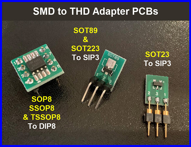
SOT23 MOSFETs can be soldered to a breadboard friendly PCB.

2 Likes

At 12V, the MOSFET’s loads draw between 200mA and 340mA. And that’s with all 50ft of the strip. The only effect is seen in a slightly bluish cast when the LEDs should be all-white. For my application of simulating day/night lighting in a diorama, the 2N7000s work acceptably. In practice, one module will drive only 5% of the 50’ strip length (so 10mA to 27mA?). A second module will drive 15% of the strip length (or 35mA to 60mA?).

The logic level MOSFETs you suggested @LarryD , were either p channel, not easily available in the US or too large. Can you suggest other logic level n channel devices? Preferably in an SOT-23 package.

  • My favourite SOT-23 P channel MOSFET is AO3401 for 100 at $2.00 AliExpress, 2 week delivery.

  • My favourite SOT-23 N channel MOSFET is IRLML2502 for 50 at $2.70 AliExpress! 2 week delivery.

1 Like
  • Good.

  • We should always check the MOSFET Drain to Source voltage to confirm the MOSFET is fully turned ON.
    This should be low, probably less than 0.1 volts.


Example:
The IRLML2502 with gate voltage = 5V has an ON resistance of ≈ 35mΩ (0.035 ohms) with the current = 2A.
35mΩ * 2A = 0.07V
.07V * 2A = 140mW