I usually use the arduino IDE to write codes but
I really need to get familiar with the avrdude and avr-gcc
thus i've been doing some research online and came across many
examples and tutorials dating back to the year 2001.
many of these examples featured atmega chips and attiny85 and other smaller versions but not the attiny16** and attiny32**
So, anyways this is what i came up with:
my example blink.c code:
//
//  main.c
//
//  Created by woot on 2024-12-01.
//
#define F_CPU 8000000L // set internal clock to 8MHz
#include "blink.h"

int main(void)
{
    PORTA.DIR |= PIN7_bm; // 0b10000000

    while(1)
    {
        PORTA.OUT |= PIN7_bm;
        _delay_ms(500);
        PORTA.OUT &= ~PIN7_bm;
        _delay_ms(500);

    }
}
Then i used
Blockquote avr-gcc -O -mmcu=attiny1616 blink.c -o ./blink.o
to generate an obj file. And then
Blockquote avr-objcopy -O ihex blink.o blink.hex
to get a hex file.
Everything was "OK" without any errors
Now my problem is that If i have to burn the code to the
mcu, I have to use the avr-dude command and include the fuse bit settings.
With many tutorials I've come across and researches I've done
I can't seem to find a way to get the right fuse bits for the attiny1616
I have looked into the arduino terminal while it was compiling and burning the code to the mcu and i noticed this:
UPDI programming for Arduino using a serial adapter
Based on pymcuprog, with significant modifications
By Quentin Bolsee and Spence Konde
Version 1.2.3 - Jan 2022
Using serial port /dev/cu.wchusbserial640 at 230400 baud.
Target: attiny1616
Set fuses: ['0:0b00000000', '2:0x01', '6:0x04', '7:0x00', '8:0x00']
Action: write
File: /var/folders/wt/ry3kx5w5085by50l_4jm2ldw0000gn/T/arduino_build_850577/Blink.ino.hex
pymcuprog.programmer - INFO - Setting up programming session for 'attiny1616'
pymcuprog.deviceinfo.deviceinfo - INFO - Looking for device attiny1616
pymcuprog.serialupdi.physical - INFO - Opening port '/dev/cu.wchusbserial640' at '115200' baud
pymcuprog.serialupdi.link - INFO - STCS 08 to 0x03
pymcuprog.serialupdi.link - INFO - STCS 06 to 0x02
pymcuprog.serialupdi.link - INFO - LDCS from 0x00
pymcuprog.serialupdi.link - WARNING - UPDI init failed: Can't read CS register.
pymcuprog.serialupdi.physical - INFO - Sending double break
pymcuprog.serialupdi.physical - INFO - Double-break sent. Retrying.
pymcuprog.serialupdi.physical - INFO - Opening port '/dev/cu.wchusbserial640' at '115200' baud
pymcuprog.serialupdi.link - INFO - STCS 08 to 0x03
pymcuprog.serialupdi.link - INFO - STCS 06 to 0x02
pymcuprog.serialupdi.link - INFO - LDCS from 0x00
pymcuprog.serialupdi.link - INFO - UPDI init OK
pymcuprog.serialupdi.link - INFO - STCS 06 to 0x02
pymcuprog.serialupdi.link - INFO - Setting UPDI clock to 8 MHz
pymcuprog.serialupdi.link - INFO - STCS 02 to 0x09
pymcuprog.serialupdi.physical - INFO - Switching to '230400' baud
pymcuprog.serialupdi.application - INFO - SIB: 'tinyAVR P:0D:0-3M2 (01.59B15.0)'
pymcuprog.serialupdi.application - INFO - Device family ID: 'tinyAVR'```
Set fuses: ['0:0b00000000', '2:0x01', '6:0x04', '7:0x00', '8:0x00']
[ATTINY1614/ATTINY1616/ATTINY1617 TINYAVR 8-BIT MICROCONTROLLER](https://onlinedocs.microchip.com/oxy/GUID-C541EA24-5EC3-41E5-9648-79068F9853C0-en-US-3/GUID-854D3EDD-FE95-446A-9F5D-D2DF94C9F3AE.html)

So with this, how do I set the fuse bits using avrdude and then
burn the code to the mcu ?

Thanks
First, you'll need a version of avrdude that includes support for the tiny-1 series (and the UPDI programming protocols.) (You'll notice that the Arduino upload is using "pymcuprog" rather than avrdude.)
Thanks for mentioning. While playing a little with Avrdude version 8.0 and a Attiny204, I am now able to read & write all the fuses. I also stumbled upon the -t (terminal) command:
Wow! Thanks for the quick help guys!
Time is a luxury I can't afford nowadays.
I will try that right away.
westfw, If i may ask..
I suppose ones the the fuses are set, i need not set it every time
I'm uploading the hex file to the MCU. Is this correct ?
I believe the only reason why the Arduino IDE always sets the fuses at every during upload is be cause it doesn't know if the board or the mcu fuses are already set ?
Also what are the differences between -Ufuse, wdtcfg and Uosccfg
and more importantly, where do i go to learn all these ??
I have come across this documentation
I suppose, all the informations are in there ?
hmeijdam, you run the execution file avrdude.exe ?
I never have to use the .exe i have the avrdude installed using brew
I also see you're using the version 8.0
I'm still stuck at 6.3 guess there shoudn't be any issues upgrading
Also, another question, I'm using L as in long and not UL as in unsigned long when setting the clock speed. The value being 8000000 - 8MHz
I suppose that wont make any difference, right ?
Thanks again
I believe the only reason why the Arduino IDE always sets the fuses at every during upload is be cause it doesn't know if the board or the mcu fuses are already set ?
Sounds reasonable. It won't (can't) set the fuses if you're using a bootloader, but with the non-bootloader upload, it pretty much has to assume a blank chip.
Also what are the differences between -Ufuse, wdtcfg and Uosccfg
and more importantly, where do i go to learn all these ??
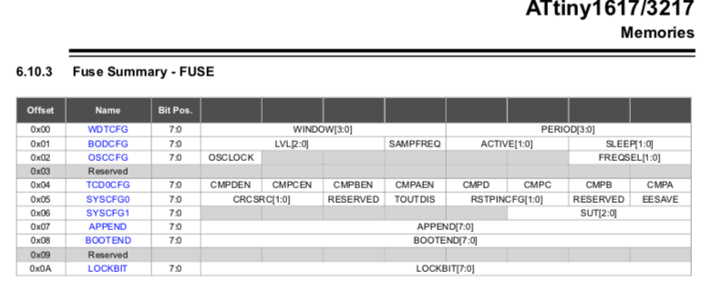
Those are described in the datasheet for the chip you are using.
The "wdtcfg" and similar names are the "functional" names that are just aliases for the numbered "fuse0" and etc names. (older avrs had things like "high" and "low" fuses where individual bits had significance. Memory (for the fuses) is apparently easier now, and the newer avrs dedicate entire bytes to some functions.)
For example, for ATtiny1617:
hahaa! everything is working! finally!
hmeijdam, Thanks!
-c serialupdi -P COM4 -p t204 -t -v -v
Is very helpful.
westfw,
Thanks a lot! the informations are indeed right there in the datasheet.
By the way, I'm seeing some strange outputs here..
Is this normal ?
the F_CPU is set at 8000000L
when i pay attention to the _delay_ms(500);
between the on and off of the led..
it's not 500ms in on and 500ms off
When i count the seconds, the led stays on 1 second and stays off 1 second.
I then changed the delay_ms to 2000
then the led stays on 5 seconds and 1 seconds off..
I had to set the F_CPU to 4MHz to get the right frequency in delay.
This is very exciting but am i missing something in regards to the fuse settings or something ? By the way I'm using the internal clock
thus no external crystal.. perhaps using F_CPU isn't the right definition ?
from the Arduino IDE, i can choose either 8MHz or 16MHz
but that doesn't affect delay or perhaps i shouldn't be using
_delay_ms() or _delay_us() ??
Thanks again ver very much guys!!!
This is far more exciting than using the IDE
Unlike earlier AVRs, the clock is not entirely controlled by the fuses.
It'll default to the internal clock, but there is also a default divisor of 6!
You'll need to set MCLKCTRLB as appropriate for your other configuration.
Probably, you have the fuses set to have the internal oscillator run at 16MHz, and you need to set _PROTECTED_WRITE(CLKCTRL_MCLKCTRLB, (CLKCTRL_PEN_bm | CLKCTRL_PDIV_2X_gc)); to get division by 2.
westfw,
when I look at the Arduino settings in "tools"
the internal clock is set to 8MHz and of course i could also switch to 16MHz, 20MHz and so on..
then OSCCFG which is set to -Uosccfg:w:0x01:m where
FREQSEL represents the internal clock is 16MHz
Atleast, i hope i'm reading correctly, unless OSCCFG is not what i think it is. But if it is the case that OSCCFG is the internal oscillator which is set at 16MHz then perhaps doing this
#define F_CPU 8000000UL
is redundant ?
I'll only need to do write something like this:
void Clock_Something_Setup(void) {
	// 16MHz prescaled by 2
	_PROTECTED_WRITE(CLKCTRL.MCLKCTRLB, (CLKCTRL_PEN_bm | CLKCTRL_PDIV_2X_gc));
}```
Well, Im confused.
The line of code above is only relevant if
#define F_CPU 8000000UL
exists but then assuming it didnt exist then by
-Uosccfg:w:0x01:m
The internal F_CPU will be 16MHz
but then again there neednt be a division on the clock.
Thus the _delay_ms(); would be accurate, at 16MHz  ??
Is are F_CPU and FREQSEL the same ?? :thinking:
I believe not since FREQSEL can be only 16MHz or 20MHz
while F_CPU can be any of these 2 values or less.
But then if FREQSEL is 16MHz then i also define F_CPU as
16MHz then what ? is there a conflict ??
I'll test all this out after work.
Thanks for the default divisor of 6
hmeijdam,
Thank you very much for this example.
I previously did what i said i was going to with the void Clock_Something_Setup(void) { // 16MHz prescaled by 2 _PROTECTED_WRITE(CLKCTRL.MCLKCTRLB, (CLKCTRL_PEN_bm | CLKCTRL_PDIV_2X_gc)); }
the _delay_ms() worked perfectly as i wanted but only when F_CPU is 8MHz
Your example is just perfect + Im horrible at naming functions.
I can imagine not many people that makes use of this micro controllers
in their profession makes use of functions such as the F_CPU_init ();
because I've come across many tutorials and examples and I've seen
non of this CPU speed initialization.
for me, this really helps a lot.
Ohh yea.. one last question..
Can i use the updi programmer to output texts in console ??
like putty or the arduino console ??
Most of the tutorials maybe use setup() and loop() and then the initialization is invisible to the user.
I saw a topic recently that some smart guy made a print/debug function via UPDI by using the GPIO registers as exchange point for data. You need a script on your PC to use it. I have tested it and it worked. Let me see if I can find it.
Actually, it's relatively common to have to remind new users of "bare metal" AVRs that setting F_CPU doesn't actually DO anything to the microcontroller; it merely informs various clock-dependent software features (like _delay_ms() and UART bitrate settings) how the clock is supposed to have been initialized.
It's less common in the Arduino space, because the environment usually takes care of things, but you still see people who try to run on a "brand new bare chip" without setting the fuses get surprised when their application runs 8x slower than expected.
(by ALWAYS starting up on the internal clock divided by 6, the new AVRs avoid the possibility of "bricking" the chip through bad fuses settings.)
hmeijdam,
Thanks Python script suggestion,
I've tried it on my mac, it works.
westfw,
It makes me wonder, prior to using F_CPU_Init();
based on the fuse settings the internal clock was set to 16MHz
and _delay_ms wasn't giving me the right time until i set
the F_CPU to 4MHz . So why did 4MHz gave me the right delay
when all the others did not ? like how did the 4MHz affected the internal clock ?? I guess i'll never know until I really gain more experience in understanding the datasheet.
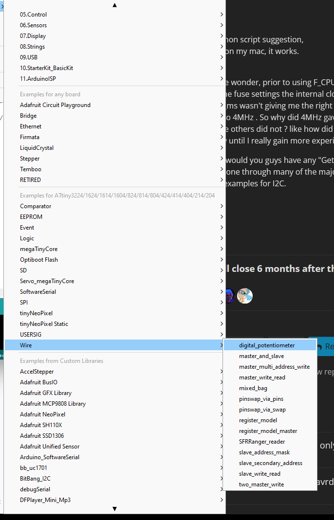
by the way would you guys have any "Getting started I2C examples" ??
So far I've gone through many of the majority of the "getting started" examples but i have yet to find examples for I2C.
Not really with the Arduino.
I was looking for something like this Getting Started with ADC
but with I2C(TWI)
I'm very perplexed that they've made many of these "Getting Started examples" of the GPIO, ADC, some Interrupts and the PWM but not I2C.