Using modbusmaster with ESP32, MAX485 & RK330-01B

Hello everyone, this is my first post in Arduino Forum, and I am quite a beginner in using RS485 sensors, as I am having some trouble understanding Modbus RTU. Firstly I would like to thank everyone for taking your time to help me in this matter. I really appreciate the guidance and advices given here :slight_smile:

I would like to use a RS485 based sensor with my NodeMCU ESP32 by using MAX485 converter.

Below is the wiring diagram for my setup:

And below is the code I used.

#include <ModbusMaster.h>

#define MAX485_DE_RE 4

ModbusMaster node; //object node for class ModbusMaster

//Initialize the ModbusMaster object as node
//ModbusMaster node;

void preTransmission()
{
  digitalWrite(MAX485_DE_RE, HIGH);
}

void postTransmission()
{
  digitalWrite(MAX485_DE_RE, LOW);
}

void setup()
{
  pinMode(MAX485_DE_RE, OUTPUT);

  digitalWrite(MAX485_DE_RE, LOW);

  Serial.begin(115200);
  
  // Transmission mode: MODBUS-RTU, Baud rate: 9600bps, Data bits: 8, Stop bit: 1, Check bit: no
  Serial1.begin(9600);

  // Slave address: the factory default is 01H (set according to the need, 00H to FCH)
  node.begin(1, Serial1)
  node.preTransmission(preTransmission);
  node.postTransmission(postTransmission);
}
//Setup ends here

void loop()
{
  // The 03H Function Code Example: Read The Atmospheric Temperature, Humidity & Pressure
  // Host Scan Order (Slave addr:0x01): 01 03 00 00 00 03 05CB
  // Slave Response: 01 03 06 01 21 0164 2728 C76E  
  // Address of the first register Lo bytes is 00
  // Number of registers of Lo bytes is 03 
  uint8_t result = node.readHoldingRegisters( 0, 3 );
  Serial.print("result = ");
  Serial.println( result );
  
  if (result == node.ku8MBSuccess)
  {
    Serial.print("Temperature : ");
    Serial.println(node.getResponseBuffer(0));
    Serial.print("Humidity : ");
    Serial.println(node.getResponseBuffer(1));
    Serial.print("Pressure : ");
    Serial.println(node.getResponseBuffer(2));
  }
  
  Serial.print("\n");
  delay(1000);
}

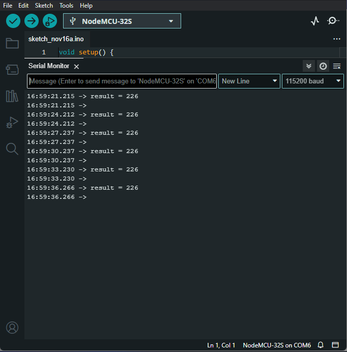
This is what I got from serial monitor:

I am not sure what else to do, I made sure the grounds to be common, I think I used the correct function code and slave address, but I still get result = 226. Im quite stuck right now, maybe I am missing something here, any help is appreciated right now, thank you very much.

Below is the datasheet of the RK330-01B for your reference:

226 is the error code that indicates a timeout whilst receiving a response from the sensor. Generally I take it that the sensor hasn't responded at all.

Note that a MAX485 based RS485 module is for use with 5V systems.

If you can locate a module that uses a MAX3485 chip or another chip designed to operate from 3.3v than that should improve your chances of success.

1 Like

Hi markd833, thank you for the heads up.

I realised by taking the power from VIN of the ESP32 (powered by the ESP's USB) to power the MX485's VCC, the voltage on the MAX485 VCC is about 4.7V.

Not taking any chances, I decided to separate the power from the ESP32 with the MAX485 first by powering it externally using my UPS module as it supposedly can output 5V. You can refer the UPS module from this ebay link.

This is a temporary solution as I need to make sure i get the reading from the sensor first, I will make a more elegant one once I figure out this problem.

Below is the modified wiring diagram:

Now I get the MAX485 VCC's voltage to be 4.96V.

But I still get the same output.

P/S: The sensor supply voltage is 12V-24VDC, hence the use of boost converter to output 12V to the sensor. I checked the voltage on the sensor's supply to be 11.98V. Do I need to use a greater voltage for the sensor or is there something else that I missed?

aadam

could happens that esp32 "close" the communication before that the whole query is sent by the max485...so try a small delay after send message and before switch to check for the answer.

The ModbusMaster library should take care of all the timing relating to switching from Tx to Rx.

Can you get any higher than 12V, as 12V is at the bottom end of the supply range. Do you have an old laptop power pack - they are usually around 19V.

In my experience, the ModbusMaster library is great when things are going well, but of limited use in situations like this.

Here's a bit of code I put together for an UNO that I've modified (hopefully correctly) for your particular setup:

#define MAX485_DE_RE 4

// half second wait for a reply
const uint32_t TIMEOUT = 500UL;

// canned message to your RS485 device
uint8_t msg[] = {0x01, 0x03, 0x00, 0x00, 0x00, 0x03, 0x05, 0xCB};

void setup() {
  Serial.begin(115200);
  Serial1.begin(9600);
  pinMode(MAX485_DE_RE, OUTPUT);
  digitalWrite(MAX485_DE_RE, LOW);
  delay(1000);
}

void loop() {
  uint32_t startTime = 0;

  Serial.print("TX: ");
  printHexMessage( msg, sizeof(msg) );

  // send the command
  digitalWrite(MAX485_DE_RE, HIGH);
  delay( 10 );
  Serial1.write( msg, sizeof(msg) );
  Serial1.flush();
  digitalWrite(MAX485_DE_RE, LOW);

  Serial.print("RX: ");
  
  // read any data received and print it out
  startTime = millis();
  while ( millis() - startTime <= TIMEOUT ) {
    if (Serial1.available()) {
      printHexByte(Serial1.read());
    }
  }
  Serial.println();
  delay(2000);
}

void printHexMessage( uint8_t values[], uint8_t sz ) {
  for (uint8_t i = 0; i < sz; i++) {
    printHexByte( values[i] );
  }
  Serial.println();
}

void printHexByte(byte b)
{
  Serial.print((b >> 4) & 0xF, HEX);
  Serial.print(b & 0xF, HEX);
  Serial.print(' ');
}

If i've not messed thing up, then it should send out a raw modbus message and then print out any bytes received. Hopefully it shows some received bytes that look like a valid Modbus reply. If you don't get any reply at all, then check the wiring to your sensor.

Do you have a USB-RS485 dongle? They can be really useful in figuring out what's going wrong.

hi...yes...it should do it...but if you google a few about "esp32 modbus problem" you will find a couple of videos that welll explain the problem..also some discussions in the ESPRESSIFF forum...i fixed it using a MAX3485 module.

PS: obviously all the "voltage reference" must be coherent.

bye

Hi @andreaber

Thank you for the input. I realised that is quite a common problem with ESP32, and I am not sure whether ModbusMaster library timing complies with ESP32 or not.

I tried to add in delay between rx and tx (500 ms, 1000 ms) but apparently does not work.

I am going to give the benefit of the doubt first based on @markd833 opinion on the timing should be fine by default. In the mean time, I need to buy the USB-RS485 dongle first to dig further on this problem. I may be short on supply voltage on the sensor as well, I need to retrofit some power adapter to fix that issue first, I'll update on the progress later.

Hi @markd833

Thank you for the advice. I am also suspecting my supply voltage to the sensor is not enough, I may need to reuse some old power adapter to fix that problem first.

I tried your code as well see whether i can get some response at all from the sensor but I got no response from the sensor:

I think the code is fine. I may need to buy the USB-RS485 dongle to see whether there is any timing issue.

I'll get the things I needed first and test it out again later. I will update here for the next progress. Thanks everyone.

The USB-RS485 dongle is very useful in these situations.

Not only can it be used to monitor the RS485 bus, but it can also be used with your PC and a Modbus app to talk to the sensor. The apps usually show you the raw Modbus message sent as well as the sensors response.

No, ESP32 is not a problem. I`m using this library for Modbus master without a problem, it works with both, hardware or software serial : https://github.com/4-20ma/ModbusMaster

It seems that whatever the issues are, they are related to using a different Modbus library - maybe one developed by Espressif.

The ModbusMaster library you are using is not the same code that Espressif use.

Hello everyone, a little update to this topic.

I managed to acquire USB-RS485 dongle to check on the sensor. Also I am using a laptop power adapter that outputs 18V for the sensor.

Using Radzio, I managed to get response from the sensor, and the reading is okay according to the datasheet.

This is the setting I used:
image

Then i tried to use my ESP32 to get response from the sensor using the code suggested by @markd833 in post #5, but I still do not get anything from the sensor to my ESP32.

My connection setup is still the same from post #3, except I changed the sensor voltage input to 18V from a laptop adapter. Even 12V from my boost converter works for the USB dongle.

Any idea what's the problem? I am really out of idea now.

I'm not familiar with Radzio. Can it show the message that it is sending to the sensor?

I'm curious as to why the screenshot seems to show 10 words when the request asks for 5.

These are the transmissions I got from the transmission log:

<tx>0x01 0x03 0x00 0x00 0x00 0x0A 0xC5 0xCD </tx>
<rx>0x01 0x03 0x14 0x00 0xE0 0x02 0x5D 0x27 0x0E 0x00 0xE0 0x00 0x00 0x00 0x00 0x00 0x00 0x00 0x00 0x00 0x00 0x00 0x01 0x77 0xC4 </rx>

<tx>0x01 0x03 0x00 0x00 0x00 0x0A 0xC5 0xCD </tx>
<rx>0x01 0x03 0x14 0x00 0xE0 0x02 0x5D 0x27 0x0E 0x00 0xE0 0x00 0x00 0x00 0x00 0x00 0x00 0x00 0x00 0x00 0x00 0x00 0x01 0x77 0xC4 </rx>

<tx>0x01 0x03 0x00 0x00 0x00 0x0A 0xC5 0xCD </tx>
<rx>0x01 0x03 0x14 0x00 0xE0 0x02 0x5D 0x27 0x0E 0x00 0xE0 0x00 0x00 0x00 0x00 0x00 0x00 0x00 0x00 0x00 0x00 0x00 0x01 0x77 0xC4 </rx>

<tx>0x01 0x03 0x00 0x00 0x00 0x0A 0xC5 0xCD </tx>
<rx>0x01 0x03 0x14 0x00 0xE0 0x02 0x5E 0x27 0x0E 0x00 0xE0 0x00 0x00 0x00 0x00 0x00 0x00 0x00 0x00 0x00 0x00 0x00 0x01 0x87 0x34 </rx>

<tx>0x01 0x03 0x00 0x00 0x00 0x0A 0xC5 0xCD </tx>
<rx>0x01 0x03 0x14 0x00 0xE0 0x02 0x5E 0x27 0x0E 0x00 0xE0 0x00 0x00 0x00 0x00 0x00 0x00 0x00 0x00 0x00 0x00 0x00 0x01 0x87 0x34 </rx>

Now I realised the data sent by Radzio is different from the one in the datasheet example, is that the problem here?

Sorry the previous one I changed the length to 10.

This is the log with length = 5

<tx>0x01 0x03 0x00 0x00 0x00 0x05 0x85 0xC9 </tx>
<rx>0x01 0x03 0x0A 0x00 0xDE 0x02 0x65 0x27 0x0C 0x00 0xDE 0x00 0x00 0x37 0x20 </rx>
<tx>0x01 0x03 0x00 0x00 0x00 0x05 0x85 0xC9 </tx>
<rx>0x01 0x03 0x0A 0x00 0xDE 0x02 0x65 0x27 0x0C 0x00 0xDE 0x00 0x00 0x37 0x20 </rx>
<tx>0x01 0x03 0x00 0x00 0x00 0x05 0x85 0xC9 </tx>
<rx>0x01 0x03 0x0A 0x00 0xDE 0x02 0x65 0x27 0x0C 0x00 0xDE 0x00 0x00 0x37 0x20 </rx>
<tx>0x01 0x03 0x00 0x00 0x00 0x05 0x85 0xC9 </tx>
<rx>0x01 0x03 0x0A 0x00 0xDE 0x02 0x65 0x27 0x0C 0x00 0xDE 0x00 0x00 0x37 0x20 </rx>
<tx>0x01 0x03 0x00 0x00 0x00 0x05 0x85 0xC9 </tx>
<rx>0x01 0x03 0x0A 0x00 0xDE 0x02 0x65 0x27 0x0C 0x00 0xDE 0x00 0x00 0x37 0x20 </rx>

You could change the array contents in my example to match those sent by Radzio where you know you should get a response from the sensor.

You can then use your USB-RS485 dongle to monitor the message sent and any response using one of the free terminal programs.

Hello everyone, here's an update from the last post.

I tried to check the transmission from ESP32 using mod_RSsim and I realised the ESP32 does not even transmit anything because the (received/sent) is (0/0).

A little bit of digging later, I realised that the serial connection of TX and RX pin need to be declared in the Serial1.begin(9600).

Here is the full fixed code:

#define MAX485_DE_RE 4

// half second wait for a reply
const uint32_t TIMEOUT = 500UL;

// canned message to your RS485 device
uint8_t msg[] = {0x01, 0x03, 0x00, 0x00, 0x00, 0x03, 0x05, 0xCB};

void setup() {
  Serial.begin(115200);
  Serial1.begin(9600, SERIAL_8N1, 16, 17);
  pinMode(MAX485_DE_RE, OUTPUT);
  digitalWrite(MAX485_DE_RE, LOW);
  delay(1000);
}

void loop() {
  uint32_t startTime = 0;

  Serial.print("TX: ");
  printHexMessage( msg, sizeof(msg) );

  // send the command
  digitalWrite(MAX485_DE_RE, HIGH);
  delay( 10 );
  Serial1.write( msg, sizeof(msg) );
  Serial1.flush();
  digitalWrite(MAX485_DE_RE, LOW);

  Serial.print("RX: ");
  
  // read any data received and print it out
  startTime = millis();
  while ( millis() - startTime <= TIMEOUT ) {
    if (Serial1.available()) {
      printHexByte(Serial1.read());
    }
  }
  Serial.println();
  delay(2000);
}

void printHexMessage( uint8_t values[], uint8_t sz ) {
  for (uint8_t i = 0; i < sz; i++) {
    printHexByte( values[i] );
  }
  Serial.println();
}

void printHexByte(byte b)
{
  Serial.print((b >> 4) & 0xF, HEX);
  Serial.print(b & 0xF, HEX);
  Serial.print(' ');
}

Then I got the connection working as below:

Here is the working code I modified from my first post:

//Defining header Files

#include <ModbusMaster.h>

#define MAX485_DE_RE 4

ModbusMaster node; //object node for class ModbusMaster

void preTransmission()
{
  digitalWrite(MAX485_DE_RE, HIGH);
}

void postTransmission()
{
  digitalWrite(MAX485_DE_RE, LOW);
}

void setup()
{
  pinMode(MAX485_DE_RE, OUTPUT);

  digitalWrite(MAX485_DE_RE, LOW);

  Serial.begin(115200);
  // Transmission mode: MODBUS-RTU, Baud rate: 9600bps, Data bits: 8, Stop bit: 1, Check bit: no
  Serial1.begin(9600, SERIAL_8N1, 16, 17);

  // Slave address: the factory default is 01H (set according to the need, 00H to FCH)
  node.begin(1, Serial1);
  node.preTransmission(preTransmission);
  node.postTransmission(postTransmission);
}
//Setup ends here

void loop()
{
  // The 03H Function Code Example: Read The Atmospheric Temperature, Humidity & Pressure
  // Host Scan Order (Slave addr:0x01): 01 03 00 00 00 03 05CB
  // Slave Response: 01 03 06 01 21 0164 2728 C76E
  // Address of the first register Lo bytes is 00
  // Number of registers of Lo bytes is 03 
  uint8_t result = node.readHoldingRegisters( 0, 3 );
  Serial.print("result = ");
  Serial.println( result );

  delay (1000);
  
  if (result == node.ku8MBSuccess)
  {
    Serial.print("Temperature: ");
    Serial.print(node.getResponseBuffer(0)/10.00);
    Serial.println("degC");
    Serial.print("Humidity: ");
    Serial.print(node.getResponseBuffer(1)/10.00);
    Serial.println("%");
    Serial.print("Pressure: ");
    Serial.print(node.getResponseBuffer(2)/10.00);
    Serial.println("mbar");
  }
  
  Serial.print("\n");
  delay(1000);
}

Thanks everyone. Appreciate all the help received.

2 Likes

No problem. Those USB-RS485 dongles are really useful in these situations.

1 Like

Hi, I am doing a very similar project where I am trying to get my RS485 sensor output to show moisture, temp, and PH but is has not been responding through my ESP32 and MAX3485A. Using your successful code in post #17 and just changing my TX,RX to match my pins 18 and 19, I am just getting "result = 226" on my serial or nothing back in my RX. Would you be able to help me too?

I even tried using a usb directly to my sensor and pc, then checking the .exe file that the company had for the sensor config to check if worked and got this so it should be responding.
image

GPIO18 -- RO
GPIO19 -- DI
GPIO4 -- RE and DE
3.3V to the MAX VCC
12V to sensor

Hi @levycake , I believe you cannot use pin 18 and pin 19 for serial communication. Unless you are using SoftwareSerial.h, which as far as I know, sometimes work and sometimes not. And it is recommended to use hardware serial for the ESP32 as you don't have to include additional library just to handle the serial communication.

1 Like