Using SD Cards on Arduino Giga?

@garyvdg i have run it with sp1 and it worked after i tested with 3 different SD modules. Thank you very much. I have spent many weeks stuck at this stage of the project. Thank you so much.

@everybody
thank you very much for your contributions. it was very helpful in the troubleshooting

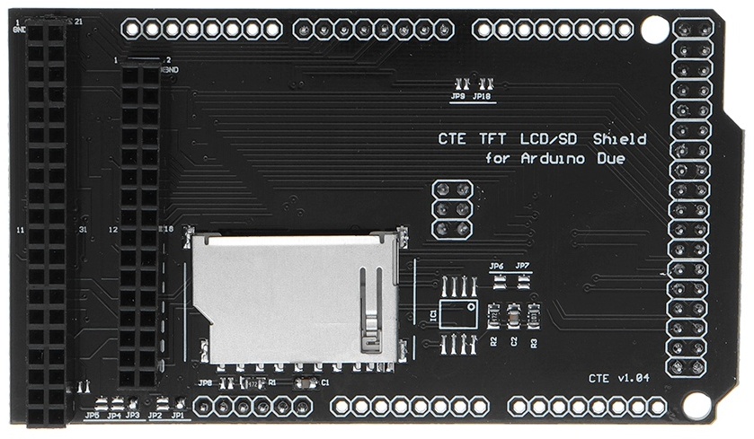
I am currently trying to use a CTE TFT LCD / SD Card Shield Expansion Board for Arduino DUE Module 3.3v.

https://www.aliexpress.com/i/3256801872252885.html?gatewayAdapt=4itemAdapt

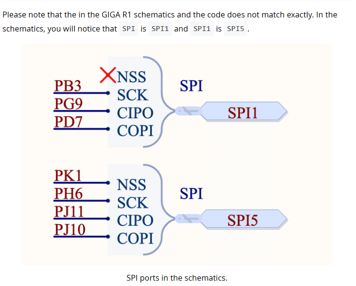
Am only using it for the SD card slot. It utilizes the ICSP port which translates to the SPI1 port on the Giga R1, and it uses pin 53 for SS.

When I run a truncated version of KurtE's example code, after changing SD_CS_PIN = 10 to SD_CS_PIN = 53, it still compiles to 10.

I added these lines to setup in order to help troubleshoot the problem.

Serial.println();
Serial.print("SS ");Serial.println(SS);
Serial.print("SCK ");Serial.println(SCK);
Serial.print("MISO ");Serial.println(MISO);
Serial.print("MOSI ");Serial.println(MOSI);
Serial.print("SDFAT FILE TYPE ");Serial.println(SDFAT_FILE_TYPE);
Serial.println();

Here is the serial output:

"SS 10
SCK 91
MISO 89
MOSI 90
SDFAT FILE TYPE 1

begin() failed
Do not reformat the SD.
No card, wrong chip select pin, or wiring error?
SdError: 0X1,0X0"

The SCK, MISI, and MOSI are correct, just the SS was not changed to 53.
IDE compiler must have a default SS with the Giga board type.

Here's the whole code:

#include "SdFat.h"
#include "sdios.h"

// SD_FAT_TYPE = 0 for SdFat/File as defined in SdFatConfig.h,
// 1 for FAT16/FAT32, 2 for exFAT, 3 for FAT16/FAT32 and exFAT.
#define SD_FAT_TYPE 1
/*
  Change the value of SD_CS_PIN if you are using SPI and
  your hardware does not use the default value, SS.
  Common values are:
  Arduino Ethernet shield: pin 4
  Sparkfun SD shield: pin 8
  Adafruit SD shields and modules: pin 10
*/

// SDCARD_SS_PIN is defined for the built-in SD on some boards.
const uint8_t SD_CS_PIN = 53;

// Try max SPI clock for an SD. Reduce SPI_CLOCK if errors occur.
#define SPI_CLOCK SD_SCK_MHZ(20)

#define SD_CONFIG SdSpiConfig(SD_CS_PIN, DEDICATED_SPI, SPI_CLOCK, &SPI1)
//------------------------------------------------------------------------------

#if SD_FAT_TYPE == 0
SdFat sd;
File file;
File root;
#elif SD_FAT_TYPE == 1
SdFat32 sd;
File32 file;
File32 root;
#elif SD_FAT_TYPE == 2
SdExFat sd;
ExFile file;
ExFile root;
#elif SD_FAT_TYPE == 3
SdFs sd;
FsFile file;
FsFile root;
#endif  // SD_FAT_TYPE

// Create a Serial output stream.
ArduinoOutStream cout(Serial);
//------------------------------------------------------------------------------
// Store error strings in flash to save RAM.
#define error(s) sd.errorHalt(&Serial, F(s))
//------------------------------------------------------------------------------
void setup() {
  Serial.begin(115200);

  // Wait for USB Serial
  while (!Serial) {
    yield();
  }

Serial.println();
Serial.print("SS ");Serial.println(SS);
Serial.print("SCK ");Serial.println(SCK);
Serial.print("MISO ");Serial.println(MISO);
Serial.print("MOSI ");Serial.println(MOSI);
Serial.print("SDFAT FILE TYPE ");Serial.println(SDFAT_FILE_TYPE);
Serial.println();

  // Initialize the SD card.
  if (!sd.begin(SD_CONFIG)) {
    sd.initErrorHalt(&Serial);
  }
  
  int rootFileCount = 0;
  if (!root.open("/")) {
    error("open root");
  }
  while (file.openNext(&root, O_RDONLY)) {
    if (!file.isHidden()) {
      rootFileCount++;
    }
    file.close();
    Serial.println (rootFileCount);
   
 }

}
//------------------------------------------------------------------------------
// Nothing happens in loop.
void loop() {}

Which pins does this shield use for spi? Ones on edge or in middle of board?
If middle then Spi object if edge Spi1

Need to make sure right object used in this line

Also if other spi objects using the same spi, dedicated may not apply

KurtE

It's defined as SPI1, as per Giga R1 specs as the serial output confirmed:
CK 91
MISO 89
MOSI 90 .

CTE adapter shield uses the middle connector, the ICSP port. No other SPI devices. Only problem I see is the SS pin is not using pin 53 as was declared:
const uint8_t SD_CS_PIN = 53;

The CTE adapter requires pin 53 as SS, but IDE COMPILER is staying with pin 10.


Again if it is getting SPI from, this connector:
image

Which connects up to:

That is the SPI object.
Which matches your pin numbers.
Try changing SPI1 to SPI in the define and see if that helps.

I believe Arduino DUE pin 53 is also pin 53 on this board :crossed_fingers:

Yes, it's that connector. SPI1 on the Giga

// SDCARD_SS_PIN is defined for the built-in SD on some boards.

const uint8_t SD_CS_PIN = 53;

// Try max SPI clock for an SD. Reduce SPI_CLOCK if errors occur.

#define SPI_CLOCK SD_SCK_MHZ(20)

#define SD_CONFIG SdSpiConfig(SD_CS_PIN, DEDICATED_SPI, SPI_CLOCK, &SPI)

returns:

SS 10

SCK 91

MISO 89

MOSI 90

SDFAT FILE TYPE 1

error: open root

SdError: 0X1,0X0

begin() failed

Do not reformat the SD.

No card, wrong chip select pin, or wiring error?

SdError: 0X1,0X0

pins_arduino.h defines 10u for both SS and SS1 if that helps

// SPI
#define PIN_SPI_MISO  (89u)
#define PIN_SPI_MOSI  (90u)
#define PIN_SPI_SCK   (91u)
// Same as SPI1 for backwards compatibility
#define PIN_SPI_SS    (10u)

#define PIN_SPI_MISO1  (12u)
#define PIN_SPI_MOSI1  (11u)
#define PIN_SPI_SCK1   (13u)
#define PIN_SPI_SS1    (10u)

Yes and NO:
That is hardware wise it is SPI1, Software wise it is SPI object...
If you look at the cheat sheet you see:


Which gives you the illusion of SPI1... (Which it is the HARDWARE SPI1 pins)

But if you look farther down on the page, you see:

So that is the reason I mention use SPI object.
Note: different underlying hardware objects versus the Arduino object is not only on SPI. For example Serial3 I believe is USART6...

So I assume it should be structured as this:

// SDCARD_SS_PIN is defined for the built-in SD on some boards.
const uint8_t SD_CS_PIN = 53;

// Try max SPI clock for an SD. Reduce SPI_CLOCK if errors occur.
#define SPI_CLOCK SD_SCK_MHZ(20)

#define SD_CONFIG SdSpiConfig(SD_CS_PIN, DEDICATED_SPI, SPI_CLOCK, &SPI)

Probably... Again I am unsure if DEDICATED will work or not...
That is, does the board have SPI Flash on it on a different CS pin, like the images sort of imply?
Likewse is there a display...
In this case the SPI may be used by multiple things, which breaks DEDICATED.

I would first probably try it with: SHARED_SPI
To see if things work, later you can try the dedicated

Still no gravy using SHARED_SPI.

Could it be that the SPI might need to be declared as soft SPI in order to bypass the default SS pin (10)? I would think not...

In the serial output:
Serial.print("SS ");Serial.println(SS);
Of course it would use the default of "10".

Is there a way to Serial print the CS pin that the actual hardware is using?

Hard to know your setup...
I don't have that adapter... My setup is like:

Sorry it is a mess of wires and the like, like Logic Analyzer hooked to USB, ILI9341 display, SD Card...

In my one sketch I was playing with: I have:

#define CS_SD 23
#define SD_CONFIG SdSpiConfig(CS_SD, SHARED_SPI, SPI_CLOCK)

Note: I did not specify SPI as it is the default...

Possible problems:

  1. Adapter connection not correct?

  2. Multiple SPI object, where the CS pins are not HIGH at startup and getting interference from them. Can fix by putting pinMode(CS_PIN_X, OUTPUT); digitalWrite(CS_PIN_X, HIGH);
    out for each CS pin, before you try the first begin.

  3. SD Card issue. i.e. not formatted to something the library expects. In your case it needs to be Fat32 (maybe Fat16) to work. If it is ExFat will not work with option 1...

3a) Not formatted in a way the it likes. I usually use the SDFormatter PC app, that formats them in a way that meets the SD Industry expectations...

  1. something else. ???

Will look into those possibilities. I tried setting pin 53 high and a couple more things. Have been searching the web and this forum for my particular CTE adapter shield. Found a few clues. I get frustrated and move on to something more productive. If and when I find a solution, will post it here. Thank you, KurtE for all your help.

Edit: Here's my setup, elegant, but if only SD worked. I have the Giga's USB port working, but was hoping SD might be faster. The crappy pic of screen is acually much better than that.


Not sure if you saw this thread:

What display and camera are you using?

Edit I see it is the giga shield...

stevebeswick:

Thanks, I suppose I could change the value of SS of SPI to 53 in pins_arduino.h.

#define PIN_SPI_SS (53u)

edit: After making this change, here's the output:

**
SS 53
SCK 91
MISO 89
MOSI 90
SDFAT FILE TYPE 1

begin() failed
Do not reformat the SD.
No card, wrong chip select pin, or wiring error?
SdError: 0X1,0X0
**

Using this to configure SD:

// SDCARD_SS_PIN is defined for the built-in SD on some boards.
const uint8_t SD_CS_PIN = 53;

// Try max SPI clock for an SD. Reduce SPI_CLOCK if errors occur.
#define SPI_CLOCK SD_SCK_MHZ(20)

#define SD_CONFIG SdSpiConfig(SD_CS_PIN, DEDICATED_SPI, SPI_CLOCK, &SPI)

Correct pins now, but still not finding SD.

KurtE:

Made the changes to SdFatConfig.h. Should be quite helpful when I get the CTE shield working, or when using a different SD card module.

Makes no difference on what the SS is set to. Almost all libraries that use SPI, work with any IO pin, as they simply do digitalWrites to set high and low... (Or faster versions of digitalWrite). It uses the pin you pass in.

Kurt E:

As stevebeswick pointed out, pins_arduino.h defaults to SS 10 for both SPI and SPI1.

After editing #define PIN_SPI_SS (10u) to #define PIN_SPI_SS (53u), at least now it's using the SS pin the CTE shield requires. (I think...). Note the image I posted earlier, the one with pin assignments.

No, you don't need the level shifting. Look for something like this.

You could get away with a SD card "socket" if you could solder to it. You will be connecting directly to the SD card contacts, no electronics required.

yep - I have one similar to that as I mentioned in the posting:

That you can see in Posting #32