This may be a more general question to configuring the SAMD21 Architecture using Arduino as opposed to Atmel Studio so I'd really appreciate a sanity check and best practice tips. I've been able to locate a few posts about using SDA/SCL as outputs and at least one older entry that makes me question it's relevance in 2020.
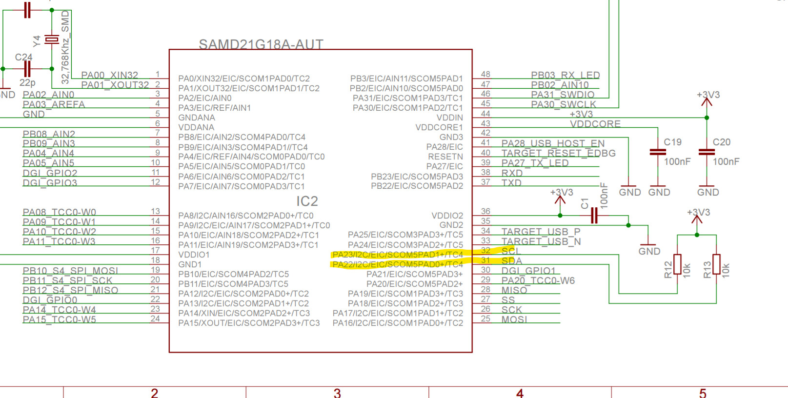
I'm using this board and need to use SDA/D20/PA22 and SCL/D21/PA23 as inputs.
Here's the schematic of the board.
Should I be using the macros from variant.h
#define PINS_COUNT           (PINCOUNT_fn())
#define NUM_DIGITAL_PINS     (20u)
#define NUM_ANALOG_INPUTS    (6u)
#define NUM_ANALOG_OUTPUTS   (1u)
#define analogInputToDigitalPin(p)  ((p < 6u) ? (p) + 14u : -1)

#define digitalPinToPort(P)        ( &(PORT->Group[g_APinDescription[P].ulPort]) )
#define digitalPinToBitMask(P)     ( 1 << g_APinDescription[P].ulPin )
//#define analogInPinToBit(P)        ( )
#define portOutputRegister(port)   ( &(port->OUT.reg) )
#define portInputRegister(port)    ( &(port->IN.reg) )
#define portModeRegister(port)     ( &(port->DIR.reg) )
#define digitalPinHasPWM(P)        ( g_APinDescription[P].ulPWMChannel != NOT_ON_PWM || g_APinDescription[P].ulTCChannel != NOT_ON_TIMER )
I see this is how the pin/ports are defined in samd21g18au.h
#define PIN_PA22  22  /**< \brief Pin Number for PA22 */
#define PORT_PA22        (1ul << 22) /**< \brief PORT Mask  for PA22 */
I see in variant.cpp that these pins can be configured as external interrupts (which is what I need)
 * | 20 | SDA |  PA22  | SDA | EIC/EXTINT[6]  PTC/X[10] *SERCOM3/PAD[0] SERCOM5/PAD[0] TC4/WO[0] TCC0/WO[4]
 * | 21 | SCL |  PA23  | SCL | EIC/EXTINT[7] PTC/X[11] *SERCOM3/PAD[1] SERCOM5/PAD[1] TC4/WO[1] TCC0/WO[5]
It took me all afternoon to just get this far
I found this solution but I have no idea how to apply it and this looks like an old way to do it
#define PIN_10_PORT 0
#define PIN_10_PIN 18

#define PIN_11_PORT 0
#define PIN_11_PIN 16

#define RING_PORT_OUTSET PORT->Group[PIN_10_PORT].OUTSET.reg
#define RING_PORT_OUTCLR PORT->Group[PIN_10_PORT].OUTCLR.reg
#define RING_PORT_OUT_MASK (1UL << PIN_10_PIN)

#define RING_PORT_IN PORT->Group[PIN_11_PORT].IN.reg
#define RING_PORT_IN_MASK (1UL << PIN_11_PIN)

void setup() {
  // set 10 to output
  PORT->Group[PIN_10_PORT].DIRSET.reg = (uint32_t)(1 << PIN_10_PIN);

  // set 11 to input
  PORT->Group[PIN_11_PORT].PINCFG[PIN_11_PIN].reg = (uint8_t)(PORT_PINCFG_INEN);

  // do loop
  while (1) { // no loop just c
    RING_PORT_IN & RING_PORT_IN_MASK ? RING_PORT_OUTCLR = RING_PORT_OUT_MASK : RING_PORT_OUTSET = RING_PORT_OUT_MASK;
  }
}

void loop() {

}
I don't know if I need to setup the pinmux and assign the function for external interrupts and I don't know the right way to do this.
I know that configuring this normally abstracted stuff is difficult but I am completely out of other digital pins. I know this is going to come up again so I'd like to get past it.
I don't want to detract from a solution. I don't want to avoid this anymore. What's the 2020 solution for this?