I just bought a "MKR 1010 Wifi" board, successfully connected it to Wifi an now I am trying to receive data on the serial interface.
I first tried port 13 and the pre-defined Serial1 to receive data. After [i]Serial1.begin(115200)[/i], I check the status with * *Serial1.available()* *
, and this returns false.
Searching Google, I found that maybe Wifi is already using Serial1 (don't know if that is true, since further attempts did not provide a solution either). So I tried to define my own serial on pins 0 & 1
jjkoenen:
now I am trying to receive data on the serial interface.
Please provide more details about what you're doing.
What are you receiving data from?
How is it connected to the MKR WiFi 1010?
jjkoenen:
I first tried port 13
What do you mean by "port 13"?
jjkoenen:
After [i]Serial1.begin(115200)[/i], I check the status with * *Serial1.available()* *
, and this returns false.
Are you sure the device is sending data to the MKR WiFi 1010? How do you know this?
jjkoenen:
Searching Google, I found that maybe Wifi is already using Serial1 (don't know if that is true, since further attempts did not provide a solution either).
Thanks for your reply. I apologize if I am not using the correct terminology, but I am new to this. Also, I misunderstood the workings of Serial1.available(). I though it returned a port status (successfully opened or not).
The project I am trying to realize is described here: Fun met Slimme meter.
Unfortunately it is in Dutch, but basically it comes to this:
The project aims to read out the digital meter in my home.
On a breadboard, I realized the small circuit as illustrated in the third figure (see link)
On the RJ11 cable to the meter, I connect pin 2 with the 5V pin of my arduino (while powered via USB). I connect pin 3 to GND of my arduino. Where 3V3 is indicated, I connect to VCC of my arduino and and where D5 is indicated, I connect to pin 13 (RX) of my arduino.
I don't have an oscilloscope, so I can't verify what is actually on the line, but the meter is active and should produce data. Since my call to Serial1.available() returns false, the arduino is not able to pick up the data.
Others have successfully read data, using the same electronic circuit, I am now trying with my MKR 1010 Wifi what the author did with a WeMos D1 Mini.
jjkoenen:
I apologize if I am not using the correct terminology, but I am new to this.
No worries. I understand now what you meant by "port". In the Arduino world, we call that a "pin" (e.g., "pin 13"). The term "port" is almost always used to refer to serial ports (e.g., COM13).
jjkoenen:
The project aims to read out the digital meter in my home.
On a breadboard, I realized the small circuit as illustrated in the third figure (see link)
On the RJ11 cable to the meter, I connect pin 2 with the 5V pin of my arduino (while powered via USB). I connect pin 3 to GND of my arduino. Where 3V3 is indicated, I connect to VCC of my arduino and and where D5 is indicated, I connect to pin 13 (RX) of my arduino.
It seems correct.
Please post the Arduino sketch you're using with Serial1.
Unfortunately, I am not getting the response I expect yet.
In the Serial monitor, I am seeing
ets Jun  8 2016 00:22:57
ets Jun  8 2016 00:22:57


rst:0x1 (POWERON_RESET),boot:0x33 (S
rst:0x1 (POWERON_RESET),boot:0x33 (S
First, I thought it was the input from the port I was reading and dumping to Serial, but searching Google made me realize, these are messages from my Arduino.
Looks like I'm not there yet. If you have any ideas, I'm sure it would help.
In any case, thank you for the help so far.
Searching Google, I found that maybe Wifi is already using Serial1 (don't know if that is true, since further attempts did not provide a solution either).
That is not true.
Well, I must confess that it is my statement which was not true. Even though the ublox NINA-W102 WiFi module is normally controlled over the SPI1 bus, there is also a connection on Serial1 primarily used for updating the firmware on the NINA module. These messages you're seeing are coming from the NINA module. There is a nice explanation of what it means here:
It's the sign-on message of the ROM; it's the first thing that gets printed after the ESP32 powers on and the CPU starts up. It means the ROM for the ESP32 was compiled on Jun 8, slightly past midnight, possibly by a set of tired colleagues happy they finally could go home. I think ets stands for Espressif Task Scheduler; that name is a remnant of the ESP8266 ROM code and the scheduler that underpinned the non-os SDK for that, which was also used for some things in ROM.
So you will see this only when the board is powered on or after a reset.
OK, thanks for clearing this out, so that means ...
I'd better configure another PIN as RX and stop using "13->RX" while using the Wifi at the same time.
On my previous attempts, nothing appeared on the Serial1. Now that I figured out that I need to feed a signal to my digital meter first, I get input on Serial1, but as it turns out, for some reason, my board is resetting and I was reading data from the NINA module.
First things first: I reverted my code back to my first post (PIN "1" as RX).
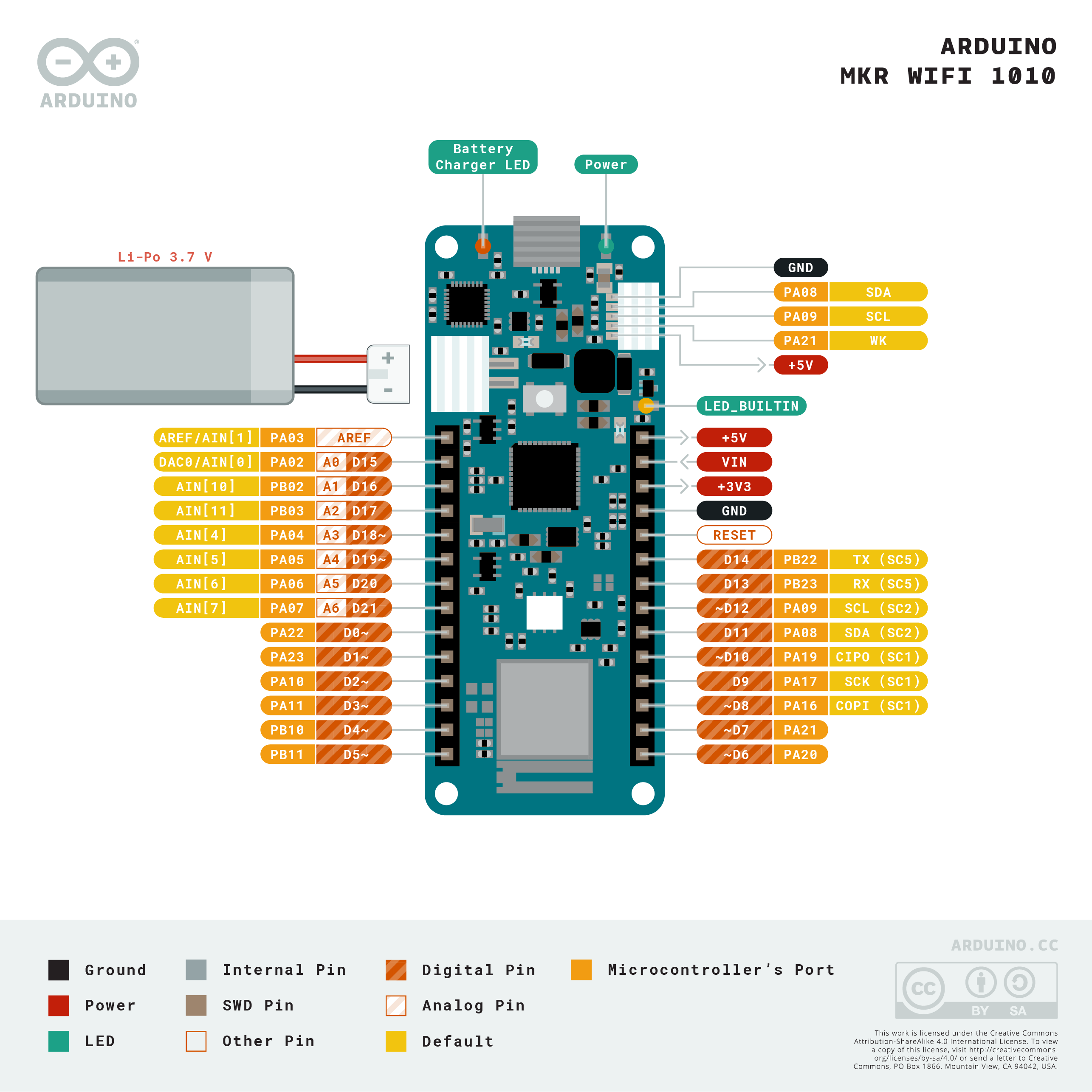
Unfortunately, I do not receive any data on that PIN, so I am wondering if PIN1 is what I think it is: (https://content.arduino.cc/assets/Pinout-MKRwifi1010_latest.png) PA23/D1 is indicated on my board as "1". Am I using the right PIN?