Looking for some help with a weird issue I have. I'm trying to create a button box that uses SPST switches to act as a toggle for a keystroke but want they keystroke to register once for every time the switch changes position (keystroke when switched to on and keystroke when switched to off). What i have works perfect for use with pin 13 but any of the other pins i use, seems to just loop through and print keystrokes randomly. Additionally, i have these switches mounted to a steel plate and oddly enough i can start and stop the printing by just resting my finger on the steel plate. None of the wires are touching the steel plate nor is the arduino which is mounted on the plate using double sided tape on the clear plastic mount that came with the Leonardo board.
Any help would be appreciated. Code is below but is only partial do simplify things while troubleshooting.
#include <Keyboard.h>
int sw1;
int sw2;
int sw3;
int sw4;
int sw5;

void setup() {
  // put your setup code here, to run once:
pinMode(9, INPUT);
pinMode(10, INPUT);
pinMode(11, INPUT);
pinMode(12, INPUT);
pinMode(13, INPUT);
Keyboard.begin();
int sw1 = digitalRead(9);
int sw2 = digitalRead(10);
int sw3 = digitalRead(11);
int sw4 = digitalRead(12);
int sw5 = digitalRead(13);
}
void loop() {
  // put your main code here, to run repeatedly:

if ((digitalRead(13) == LOW) && (sw5 == 1)){
    sw5 = 0;
  Keyboard.print('E');
  delay(50);
};


if ((digitalRead(13) == HIGH) && (sw5 == 0)){
    Keyboard.print('E');
    sw5 = 1;
    delay(50);};

if ((digitalRead(11) == LOW) && (sw4 == 1)){
    sw4 = 0;
  Keyboard.print('A');
  delay(50);
};


  if ((digitalRead(11) == HIGH) && (sw4 == 0)){
    Keyboard.print('B');
    sw4 = 1;
    delay(50);};

}
What, if anything, is keeping your switch pins at a known state at all times, or are they floating at an unknown state , maybe HIGH, maybe LOW, when the buttons are not pressed ?
Consider changing their pinMode() to INPUT_PULLUP to activate the built in pullup resistor to keep them normally HIGH. Change wiring to take the pins LOW when the button is pressed and adjust the program logic to match
Using pin 13 as an input for a switch can also be problematic as it has an LED or opamp connected to it on the Arduino board
You also missed to tell us how you connected the SPST switches: based on your code, you must have a pull-down resistor (typically 10k from the pin to GND). If not, that's why you get strange behaviours, you always either need to have a pull-down or a pull-up resistor. And with the latter, you must remember the switch off is read as HIGH not LOW (you could avoid the external resistor by declating the pin as INPUT_PULLUP not just INPUT).
Apart from that resistors issue, just to make things easier for you (and us), use constants to identify the pins and related switches, like this, where I included the "reversse" behaviour, using internal pullups:
#include <Keyboard.h>

// Pins configuration
const byte P_SW1 = 9;
const byte P_SW2 = 10;
const byte P_SW3 = 11;
const byte P_SW4 = 12;
const byte P_SW5 = 13;

int sw1;
int sw2;
int sw3;
int sw4;
int sw5;

void setup() {
  // put your setup code here, to run once:
  pinMode(P_SW1, INPUT_PULLUP);
  pinMode(P_SW2, INPUT_PULLUP);
  pinMode(P_SW3, INPUT_PULLUP);
  pinMode(P_SW4, INPUT_PULLUP);
  pinMode(P_SW5, INPUT_PULLUP);
  Keyboard.begin();
  int sw1 = digitalRead(P_SW1);
  int sw2 = digitalRead(P_SW2);
  int sw3 = digitalRead(P_SW3);
  int sw4 = digitalRead(P_SW4);
  int sw5 = digitalRead(P_SW5);
}

void loop() {
  // remember the reversed behaviour: switch on is LOW not HIGH!!!
  if ((digitalRead(P_SW1) == LOW) && (sw1 == HIGH)){
    sw1 = LOW;
    Keyboard.print('E'); // or whatever...
    delay(50);
  };
  if ((digitalRead(P_SW1) == HIGH) && (sw1 == LOW)){
    Keyboard.print('E'); // or whatever...
    sw5 = HIGH;
    delay(50);
  };
  if ((digitalRead(P_SW2) == LOW) && (sw2 == HIGH)){
    sw2 = LOW;
    Keyboard.print('A');  // or whatever...
    delay(50);
  };
  if ((digitalRead(P_SW2) == HIGH) && (sw2 == 0)){
    Keyboard.print('B');
    sw2 = HIGH;
    delay(50);};
  };
...and so on
If this approach works, then you could reach a higher programming level by using arrays, but we better stop here for the moment...
This is only part of my button box and also have a 2x5 matrix for some push buttons. I use pins 2-8 for that. Would it be better to use pin 0 or 1 instead of 13?
This problem does not relate to IDE version 1.x, or any other version. I will move it to a more appropriate section of the form.
You need to learn about local variables and global variables.
Pin 13 often has the on-board LED connected to it. This might explain why that pin acts differently.
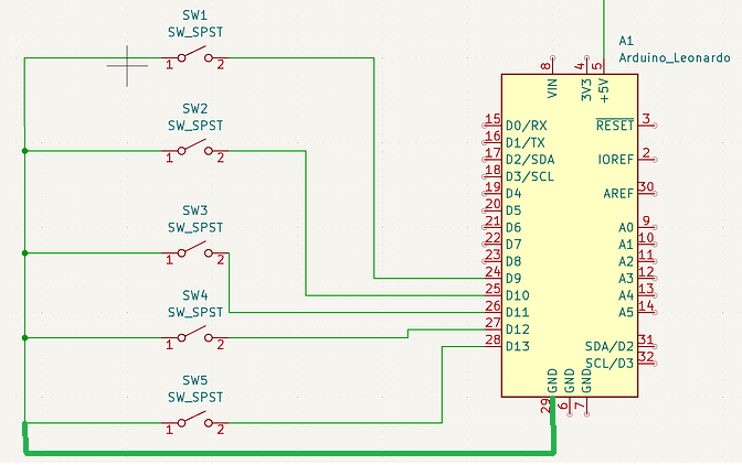
Your input pins are floating, despite the fact that you used INPUT_PULLUP mode. Please post a link to the data sheet of the switches you are using and a schematic to show how they are wired to the Leonardo.
Pins 0 and 1 are Serial RX and TX. We often use serial when debugging but it's not required. Pin 13 has the board LED.
Are 9 to 12 tied up? IIRC those are SPI/I2C pins.
Are the analog in pins tied up? They also work as digital IO.
For just 1 more pin you could make a 4x4 matrix. 5x2+6
With 4 pin SPI and a daisy-chain of input shift register chips wired to buttons (likely with pulldowns), 100's of contact switches can be polled reasonably fast. 4 pins, arbitrarily many inputs.
What would you expect the input pins to read when the switches are closed?
What would you expect the input pins to read when the switches are open? Remember that your code sets the pins to INPUT_PULLUP mode.
The correct answer to both questions is HIGH. That means your code won't be able to tell what position the switches are in by reading the input pins. They would never read LOW at all.
That's assuming your schematic is correct.
But your description of the problem tells us the pins are reading HIGH and LOW at random, influenced by nearby objects. They are floating.
In reality, they can't be connected as shown in your schematic.
My original code only used INPUT because the intent was to read the true state of the input. That way if the input pin state was different than the stored sw variable, the if statement would execute the print keystroke and change the state of the sw variable so next time it went through the loop, the only way a keystroke was executed was if the physical switch was changed again.
If my schematic for this case is not correct do you have suggestions on what to do with the switches I have to make this work?
I'm sorry, but I don't understand: how does that section might give a short between +5V and GND?
There's R4, so while the button is pressed you have a 10k Ohm resistor between +5V and GND, so inside that link flows a current I=V/R=5/10.000=0.5 mA.
Why on Earth would that be a problem?