So if i understand correctly, by using this you could send different signals through the same pin?
Yes, this technique is called "multiplexing". Each row or column of LEDs is lit in turn and so is lit for only part of the time. But because the process of scanning is so fast, and repeats many times each second, to a human eye it appears that all LEDs are lit as the same time. The disadvantage of this technique is that the LEDs do not appear as bright, but hopefully they will still be bright enough. The advantage is that, rather than 20 Arduino pins, each separately connected to an LED, only a pin for each row and a pin or each column of the matrix is required. This is similar to your keypad, where only 8 pins, not 16, are required sense the 16 keys.
Alright, thanks a lot, I will definitely try that, but just out of curiosity, would it be possible to solve this problem by adjusting the code rather than the hardware?
Yes, it would be possible, in theory.
But how hard would it be? Harder than adjusting the hardware, I'm pretty sure.
Beginners often underestimate the difficulty of getting more than one Arduino to work together in the same project. It is often the hardest part of the project to get two or more Arduino to communicate and coordinate, harder than any other part of the project.
Experts will generally avoid using multiple Arduino in a project, unless there is no other choice, or the other choices are way more expensive.
Don't forget: you can use analog pins A0-A5 as digital pins.
(Assuming you are using Uno, I don't think you mentioned what type of Arduino you are using).
If it's possible in theory, I'd love to know how I could define these pins separately! I'm really intrigued to see if I can solve this problem via code.
Hi, @doomsdayenjoyer
Can you please post a copy of your circuit, a picture of a hand drawn circuit in jpg, png?
Hand drawn and photographed is perfectly acceptable.
Please include ALL hardware, power supplies, component names and pin labels.
This will help to interpret your code.
Thanks.. Tom.. 


@doomsdayenjoyer : This is essential to see if your problems can be solved by code changes only. Every detail of your circuit/wiring is important.
It would also be helpful if you explained exactly how the project is supposed to work
I am still bemused by your use of the same pins for 2 different purposes
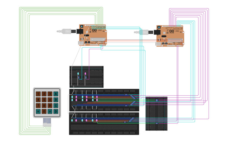
I made a rough copy of the circuit on tinkercad, it isn't 1:1 the original (mainly some pin assignements) :
https://www.tinkercad.com/things/eWLlm7G7RcK-tic-tac-toe-using-two-arduinos
If u don't have / want to make a tinkercad account heres the image and a PDF:
Tic Tac Toe using two Arduinos.pdf (12,9 KB)

(changed the links to files thanks to @UKHeliBob descripiton)
I want the circuits to work in such a way that when the red signal LED "A" is lit and I press any key from 1-9 on the keypad, a red LED will turn on in position 1-9, corresponding to which key was pressed, but when the green signal LED "B" is lit and I press 1-9, a green LED will turn on instead. In addition, pressing A on the keypad will turn on the red LED and turn off the green LED and vice versa. In addition, if I press the " * " key, all the LEDs go out and the red signal LED comes back on.
To post images etc. you need trust level 1, you can get there by:
- Entering at least 5 topics
- Reading at least 30 posts
- Spend a total of 10 minutes reading posts
Users at trust level 1 can...
- Use all core Discourse functions; all new user restrictions are removed
- Send PMs
- Upload images and attachments