It has a 200K pot at the output which allows you to adjust the boost voltage.
I thought I'd just replace this with an SPI / I2C digital pot , but then after de-soldering the pot I discovered (the hard way) that it's actually putting AC through the pot. :o
So , now I'm a bit stuck. The specs I read for the MCP digital pots sound like they only like DC across the A/B pins , and it needs to be within 0.3 V of VCC , so that's scuppered that plan, so now it looks like I'm going to have to build some kind or R-2R ladder to act as a pot ...4 bits would be enough a 16 stage charger will be plenty of flexibility.
Any ideas for circuits ? I presume I'll need a 4 channel SSR , but was wondering if anyone had any other suggestions / knew how these boost converters operate, or were already controlling the boost voltage another way ? Any suggestions welcome.
I don't know the answer to your question, however...
48V is not the correct voltage to charge a (I assume) 24 cell lead acid battery, you need 2V2 per cell, so 52V8. There are also cases where you might increase this slightly, see Battery University, which has loads of useful information. Why do you think you need to change the voltage? I am also puzzled at why you need a small variable boost converter when you have a 4000W charger.
PerryBebbington:
I don't know the answer to your question, however...
48V is not the correct voltage to charge a (I assume) 24 cell lead acid battery, you need 2V2 per cell, so 52V8. There are also cases where you might increase this slightly, see Battery University, which has loads of useful information. Why do you think you need to change the voltage? I am also puzzled at why you need a small variable boost converter when you have a 4000W charger.
Thanks for the reply Perry , think you missed the point of the boost converter, the PSU only puts out 48V .... the boost converter ups this to 57V6 , initially 2V4 per cell, and can limit the current, but then decreases to 2V3 per cell as the battery approaches full charge, then 2V2 float.... but ignore all that ... the charger works well , it's just a pain having to adjust the voltage manually as the batteries charge.
I should've just asked "How do I replace a 200K 0.5W POT with AC across it with a digitally controlled equivalent"
Spot on Perry ! Good maths, That's right ... no way the boost converter could handle 82A , but I wanted a PSU that could cover any future expansion , The biggest booster I could find on ebay was 1800W which is enough for my initial project , it's got OCP so will only ever draw a max of 37.5A .
I actually have a block of 8 10A reed relays lying around somewhere, and was going to use them but then thought SSR's might be more reliable , they're opto-isolated , but only 2A .... I'll go whip that POT off again and see how much current is going through it ... can't be much it's one of these
And the ACV can't be that high ... it was more of a tingle than a jolt when I touched it
The current through that will be milliamps at most. Never heard of a 10A reed relay!
I feel there is something I'm not getting. I am surprised that the it is AC the pot is adjusting, I expected DC as it should be in the DC feedback loop.
So did I , imagine my surprise when it zapped me ! ... apologies , I should've said 10A mechanical relay... I presumed they were reeds as they click when activated..it's basically one of these
Damn... just realised that if I use a resistor tree / ladder and I want to vary between 57V6 and 52V8 I'm probably talking about only a couple of turns of a 28 turn pot .... I also wanted to make it 'optionally' work at 36V and 24V .... so I think I'd best go stick it in a breadboard and take some measurements.... if I can work out the resistance change to cover a 5V swing I can just swap in an upper and lower resistance and just have my "digi-pot" in the middle (the 4KW PSU can output 48/36/24/12).
wonder if there's such a thing as an IC resistor tree.
Thanks evanmars , that'll save a lot of soldering.
I took the POT off last night and it's putting 70VAC across that little trimmer pot !
I got as far as figuring out that one end of the pot is shorted to the wiper, the voltage is controlled by the R between the wiper and the other end, and to get 57V out this R needs to be ~65K
I then shorted the whole thing with a clumsy probe and blew the bloody fuses.
Ordered some of amazon ... should be here by Friday ... hopefully it hasn't damaged anything else.
Apologies for my ignorance, it's 25 years since I did electronics and the memory is not what it used to be.
Problem with the resistor network IC's is they're either the same values or R-2R. I could create a binary tree , but to get a simple 4 bit tree would require 15 switches/relays/SSR's
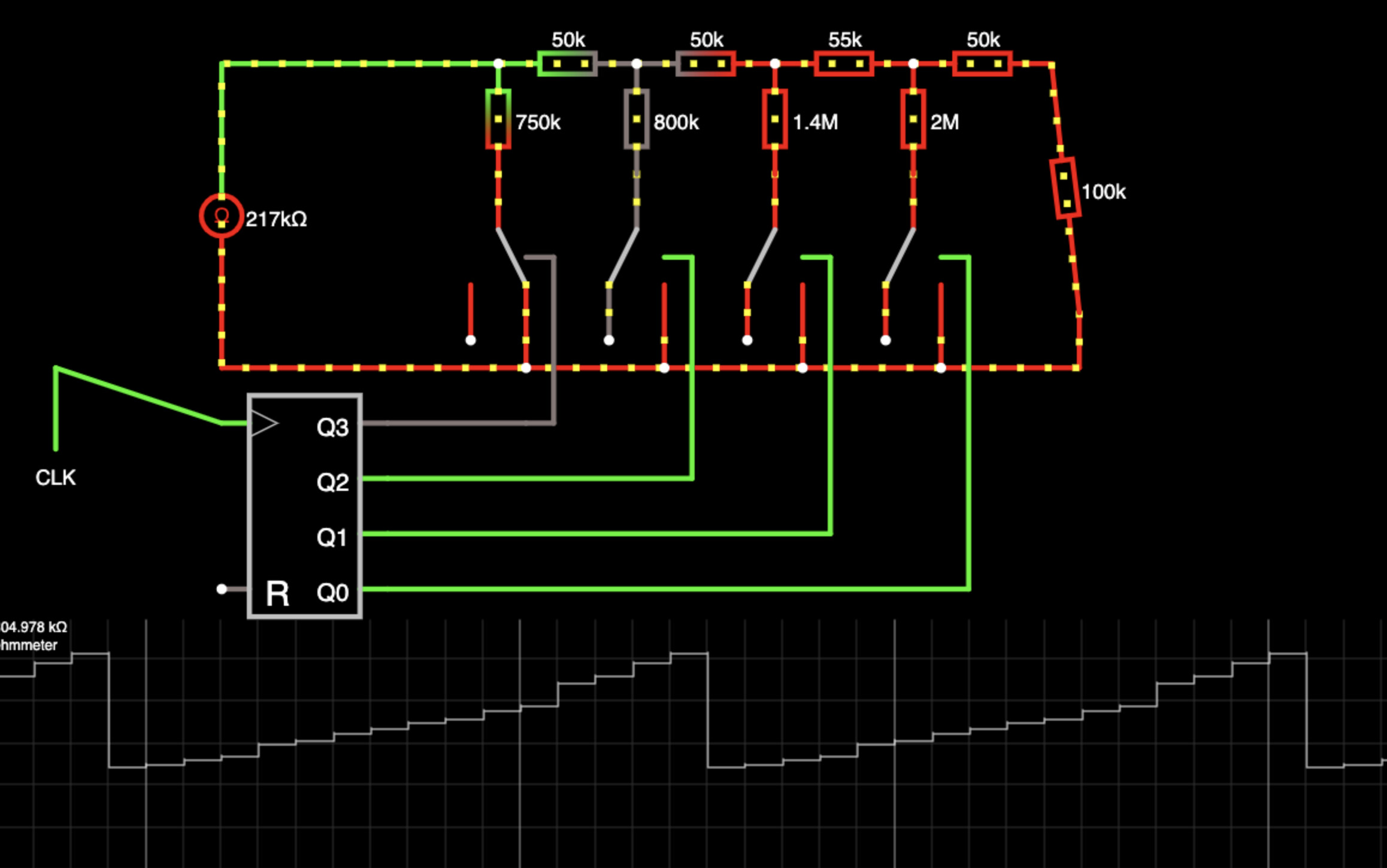
Using the same pattern as R-2R I can do a 4 bit resistor network with just 4 SSR's. I've attached a screenshot of a simulation of what I'm trying to do
Can someone tell me what formula I'm looking for here to work out these resistor values. It's a resistor ladder like an R-2R, but instead of voltage stepping linearly, I want the resistance to step up linearly... in my ignorance I've tried tweaking the resistor values manually and got it close-ish (the graph at the bottom is Resistance across the network) , but it'd be nice to do it right.
In case it helps anyone else, I got this working, and in a moment of clarity realised I didn't need a ladder network to achieve the digital pot, The attached circuit creates a perfect linear digitally controlled pot.