VL53L0X, FSR, and Relay Switch Make Serial Port Slow

Hello,

I am a newbie. I am trying to create a pneumatic fatigue tester for soft materials. I have an air-driven pneumatic cylinder connected to a solenoid (via a 5V relay switch). As the pneumatic cylinder compresses the sample, I want to measure force using a force-sensing resistor (FSR) and I want to also measure the displacement of the compression using a Time of Fight VL53L0X laser sensor. I send all data through the serial port to a python program that saves the data. My goal is to have different frequencies of loading with the fastest at a delay of 0.1 s. I'm using baud rate of 115200.

Most everything is working perfectly in pieces, but when I have everything (5V relay switch going on and off, FSR collecting data and ToF sensor reading data) my code runs slow (takes about 1 second to advance to the next step)

When I comment out the ToF reading, it goes back to running fast (a delay about .1 s).

My thought is that is something to do with sending information from ToF back to the serial port but I have not able to find others with this problem. Without the ToF sensor, the FSR and relay switch works perfectly. I can control the delay from my python program and data is saved to a file just fine (I don't think there is an issue sending and writing data). In fact, at this point, I am not even sending ToF data back to the computer. It should just read and not do anything with the reading.

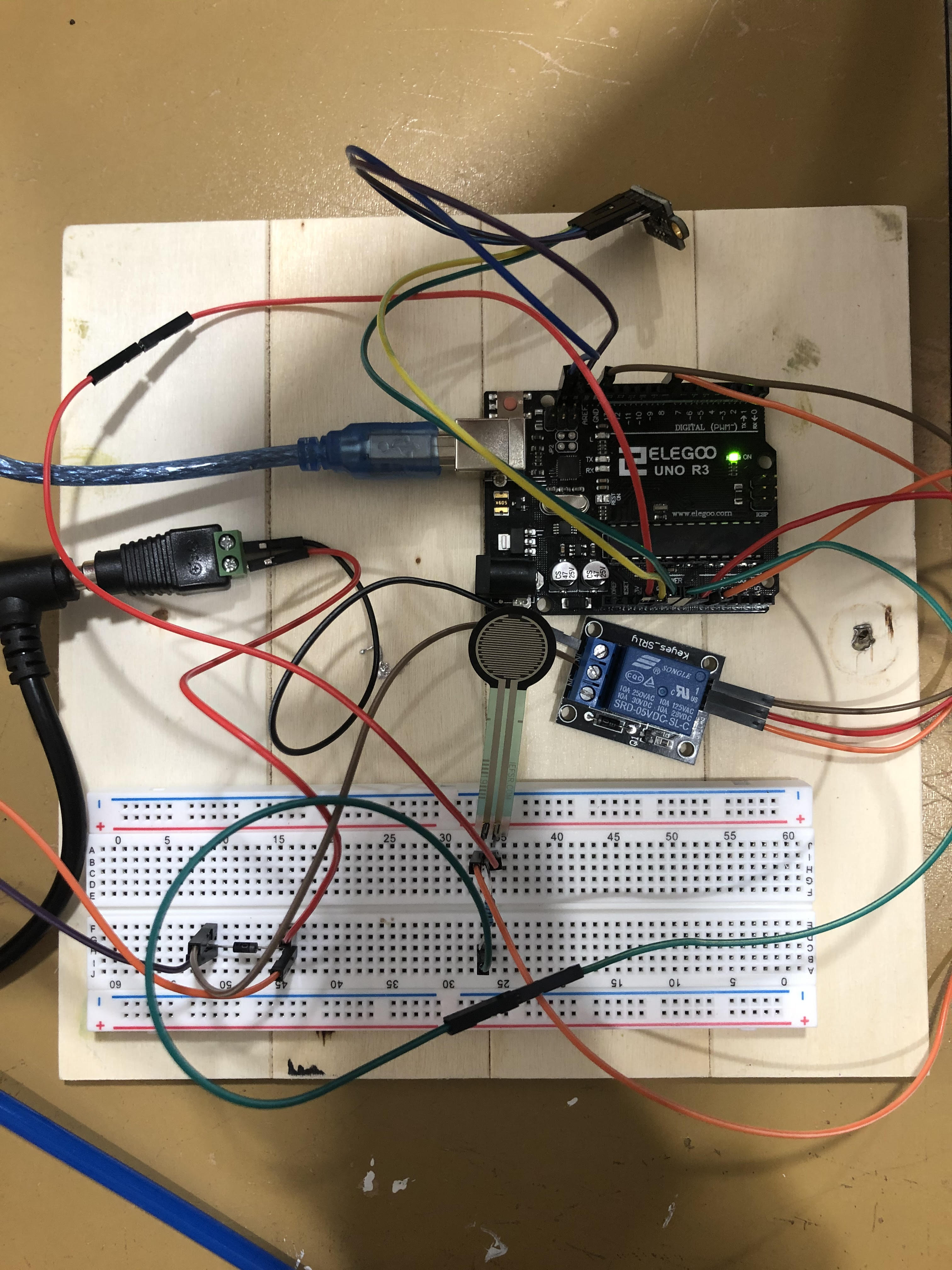
Below are details including the wiring diagram, my Arduino code, and my python file. I have also included a picture of my setup.

Any suggestions about why the slow down might be happening would be very helpful. Thank you.

Wiring diagram:

Arduino Code:

#include <Wire.h>
#include <VL53L0X.h>

VL53L0X sensor;

byte newServoPos = 0;

// Define FSR pin:
#define fsrpin A0

//Define variable to store sensor readings:
float fsrreading; //Variable to store FSR value


uint16_t dispreading;


// constants won't change
const int RELAY_PIN = 8;  // the Arduino pin, which connects to the IN pin of relay

const byte numLEDs = 2;
byte ledPin[numLEDs] = {12, 13};
unsigned long LEDinterval[numLEDs] = {200, 400};
unsigned long prevLEDmillis[numLEDs] = {0, 0};

const byte buffSize = 40;
char inputBuffer[buffSize];
const char startMarker = '<';
const char endMarker = '>';
byte bytesRecvd = 0;
boolean readInProgress = false;
boolean newDataFromPC = false;

char messageFromPC[buffSize] = {0};
long newFlashInterval = 0;
float servoFraction = 0.0; // fraction of servo range to move


unsigned long curMillis;

unsigned long prevReplyToPCmillis = 0;
unsigned long replyToPCinterval = 100;

//=============

void setup() {
  Serial.begin(115200);
  Wire.begin();
  sensor.setTimeout(500);
  
  if (!sensor.init())
  {
    Serial.println("Failed to detect and initialize sensor!");
    while (1) {}
  }
  
  // initialize digital pin 9 as an output.
  pinMode(RELAY_PIN, OUTPUT);
  
    // flash LEDs so we know we are alive
  for (byte n = 0; n < numLEDs; n++) {
     pinMode(ledPin[n], OUTPUT);
     digitalWrite(ledPin[n], HIGH);
  }
  delay(500); // delay() is OK in setup as it only happens once
  
  for (byte n = 0; n < numLEDs; n++) {
     digitalWrite(ledPin[n], LOW);
  }
  
    // initialize the servo
  //myServo.attach(servoPin);
  //moveServo();


  // Start continuous back-to-back mode (take readings as
  // fast as possible).  To use continuous timed mode
  // instead, provide a desired inter-measurement period in
  // ms (e.g. sensor.startContinuous(100)).  
  //sensor.startContinuous();
  //sensor.setMeasurementTimingBudget(20000);
  
    // tell the PC we are ready
  Serial.println("<Arduino is ready>");
}

//=============
void loop() {

  curMillis = millis();
  getDataFromPC();
  //updateFlashInterval();
  updateSelSwitch();
  //updateServoPos();
 
  
  // Read the FSR pin and store the output as fsrreading:
  fsrreading = analogRead(fsrpin);
  
  dispreading = sensor.readRangeSingleMillimeters();
  //dispreading = sensor.readRangeContinuousMillimeters();

  replyToPC();
  //Serial.println("<Msg LED1 NewFlash 1 SrvFrac 16.0000 SrvPos 0 Time 6881>");
  //flashLEDs();
  //moveServo();
}

//=============
void getDataFromPC() {

    // receive data from PC and save it into inputBuffer
    
  if(Serial.available() > 0) {

    char x = Serial.read();

      // the order of these IF clauses is significant
      
    if (x == endMarker) {
      readInProgress = false;
      newDataFromPC = true;
      inputBuffer[bytesRecvd] = 0;
      parseData();
    }
    
    if(readInProgress) {
      inputBuffer[bytesRecvd] = x;
      bytesRecvd ++;
      if (bytesRecvd == buffSize) {
        bytesRecvd = buffSize - 1;
      }
    }

    if (x == startMarker) { 
      bytesRecvd = 0; 
      readInProgress = true;
    }
  }
  
}

//=============
void parseData() {

    // split the data into its parts
    
  char * strtokIndx; // this is used by strtok() as an index
  
  strtokIndx = strtok(inputBuffer,",");      // get the first part - the string
  strcpy(messageFromPC, strtokIndx); // copy it to messageFromPC
  
  strtokIndx = strtok(NULL, ","); // this continues where the previous call left off
  newFlashInterval = atol(strtokIndx);     // convert this part to an integer, using atol, not atoi
  
  strtokIndx = strtok(NULL, ","); 
  //servoFraction = (float) atof(strtokIndx);     // convert this part to a float
   fsrreading = (float) atof(strtokIndx);     // convert this part to a float
  //Serial.print(servoFraction);
 
}

//=============
void replyToPC() {

  if (newDataFromPC) {
    newDataFromPC = false;
    Serial.print("<Msg ");
    Serial.print(messageFromPC);
    Serial.print(" NewFlash ");
    Serial.print(newFlashInterval);
    Serial.print(" SrvFrac ");
    //Serial.print(servoFraction,4);
    Serial.print(fsrreading,4);
    Serial.print(" SrvPos ");
    Serial.print(newServoPos);
    Serial.print(" Time ");
    //Serial.print(curMillis >> 9); // divide by 512 is approx = half-seconds
    Serial.print(curMillis); // divide by 512 is approx = half-seconds
    Serial.println(">");
  }
}

//============

void updateFlashInterval() {

   // this illustrates using different inputs to call different functions
  if (strcmp(messageFromPC, "LED1") == 0) {
     updateLED1();
  }
  
  if (strcmp(messageFromPC, "LED2") == 0) {
     updateLED2();
  }
}

void updateSelSwitch(){
  
  if(newFlashInterval == 1 ){
    digitalWrite(RELAY_PIN, HIGH);
  }
  if(newFlashInterval == 0 ){
    digitalWrite(RELAY_PIN, LOW);
  }
}

//=============

void updateLED1() {

  if (newFlashInterval > 100) {
    LEDinterval[0] = newFlashInterval;
  }
}

//=============

void updateLED2() {

  if (newFlashInterval > 100) {
    LEDinterval[1] = newFlashInterval;
  }
}

//=============

void flashLEDs() {

  for (byte n = 0; n < numLEDs; n++) {
    if (curMillis - prevLEDmillis[n] >= LEDinterval[n]) {
       prevLEDmillis[n] += LEDinterval[n];
       digitalWrite( ledPin[n], ! digitalRead( ledPin[n]) );
    }
  }
}

Python Code:
When I post this, I get an error that the message is too long. So I will post a reply with the code.

Picture of setup:

ArduinoPC2.ino (5.18 KB)

python-code.pdf (40 KB)

If You attache the code using code tags, upper left symbol in this window, and made the pictures show up here as well Your post would get top marks.
Several helpers can't download and read. ino files.
Are there Serial, or other prinouts in that ToF code?

rhk12:
My thought is that is something to do with sending information from ToF back to the serial port but I have not able to find others with this problem.

No need for searching, Serial output is a bottleneck in every program. Reduce the output and increase the baudrate for better overall performance.

Hi,
Welcome to the forum.

Please read the post at the start of any forum , entitled "How to use this Forum".
OR
http://forum.arduino.cc/index.php/topic,148850.0.html.
Then look down to item #7 about how to post your code.
It will be formatted in a scrolling window that makes it easier to read.

Can you please post a copy of your circuit, in CAD or a picture of a hand drawn circuit in jpg, png?

Thanks.. Tom... :slight_smile:

Thank you all for your responses. I have updated my posted to include images and code. I did get an error that my posted exceeded the limit when I added my python code, so I am including that here. I also left the pdf of the code attached.

import serial
import time
#import collections
import matplotlib.pyplot as plt
#import matplotlib.animation as animation
#from matplotlib.animation import FuncAnimation
#import numpy as np


#=====================================

#  Function Definitions

#=====================================

def sendToArduino(sendStr):
    #print(sendStr)
    ser.write(sendStr.encode('utf-8')) # change for Python3
    

#======================================

def recvFromArduino():
    global startMarker, endMarker
    
    ck = ""
    x = "z" # any value that is not an end- or startMarker
    byteCount = -1 # to allow for the fact that the last increment will be one too many
    
    # wait for the start character
    while  ord(x) != startMarker: 
        x = ser.read()
    
    # save data until the end marker is found
    while ord(x) != endMarker:
        if ord(x) != startMarker:
            ck = ck + x.decode("utf-8") # change for Python3
            byteCount += 1
        x = ser.read()
    
    return(ck)


#============================

def waitForArduino():

    # wait until the Arduino sends 'Arduino Ready' - allows time for Arduino reset
    # it also ensures that any bytes left over from a previous message are discarded
    
    global startMarker, endMarker
    
    msg = ""
    while msg.find("Arduino is ready") == -1:

        while ser.inWaiting() == 0:
            pass
        
        msg = recvFromArduino()

        print (msg) # python3 requires parenthesis

        
#======================================

def runTest(td):
    numLoops = len(td)
    waitingForReply = False

    n = 0
    while n < numLoops:
        teststr = td[n]

        if waitingForReply == False:
            sendToArduino(teststr)
            #print ("Sent from PC -- LOOP NUM " + str(n) + " TEST STR " + teststr)
            waitingForReply = True

        if waitingForReply == True:

            while ser.inWaiting() == 0:
                pass
            
            dataRecvd = recvFromArduino()
            #print ("Reply Received  " + dataRecvd)
            n += 1
            waitingForReply = False

            #print ("===========")

        time.sleep(.1)
        # 5 position is the new servoFraction
        # 9 position is the time in ms 
        # split up char 
        data1 = dataRecvd.split(" ") #maxsplit


    return data1;


#======================================

# THE DEMO PROGRAM STARTS HERE

#======================================


if __name__ == '__main__':
    
    # NOTE the user must ensure that the serial port and baudrate are correct
    # serPort = "/dev/ttyS80"
    serPort = "/dev/ttyACM0"
    baudRate =  115200; #57600;
    ser = serial.Serial(serPort, baudRate)
    # Toggle DTR to reset Arduino
    ser.setDTR(False)
    #time.sleep(1)
    # toss any data already received, see
    # http://pyserial.sourceforge.net/pyserial_api.html#serial.Serial.flushInput
    ser.flushInput()
    ser.setDTR(True)
    
    print ("Serial port " + serPort + " opened  Baudrate " + str(baudRate))
    
    
    startMarker = 60
    endMarker = 62
    
    
    waitForArduino()
    
    
    testData = [];
    testData.append('inital');
        
    #fig = plt.figure();
    #ax = fig.add_subplot(111)
    
    max_steps = 10000;
    time_s = 0;
    time_switch = 10.0; # 10 seconds
    switch_counter = 2; 
    new_time_switch = time_switch;
    switch_flag = 0;
    step_duration = 0.0
    num1 = 0;
    xdat=[];
    ydat=[];
    f = open("/home/rhk12/code/output.txt", "w")

    for i in range(1,max_steps):
        start_time = time.time();
        str1 = '<LED1,';
        
        max_arduino_int = 2147483647; # 2,147,483,647
        
#        if (time_s >= new_time_switch):
#            new_time_switch = new_time_switch + time_switch;
#            switch_flag = 1;
#        
#        if (switch_flag == 1):
#            if (num1 == 0):
#                num1 = 1;
#                switch_flag = 0;
#            if (num1 == 1 and switch_flag == 1):
#                num1 = 0;
#                switch_flag = 0;
                
        if (i % switch_counter == 0 ):
            switch_flag = 1;
        
        if (switch_flag == 1):
            if (num1 == 0):
                num1 = 1;
                switch_flag = 0;
            if (num1 == 1 and switch_flag == 1):
                num1 = 0;
                switch_flag = 0;                
                
        if num1 >= max_arduino_int:
            print('num1 is too big!')
            
        str2 = '{0:9d},'.format(num1);
        #str2 = '{0:05d}.00>'.format(1);
        # remove the decimal point make integer for sending
        num2 = 12.1234; # only can send info with 7 digits
        if num2 >= max_arduino_int:
            print('num2 is too big!')
            
        str3 = '{0:9.6f}>'.format(num2);
        #str4 = '{0:8.3f}'.format(12345.001);
        #str1 = '<LED1,200,11113.00>'
        str4 = str1 + str2 + str3;
        #print(str3)
        testData[0] = str4;
        #print('length of str3 =',len(str4))
        
        data1 = runTest(testData);
        #print(data1);
        time_s = float(data1[9])/1000.0; # convert ms to s
        
    
        # plotting starts below
#        pltInterval = 50    # Period at which the plot animation updates [ms]
#        maxPlotLength = 100
#        xmin = 0
#        xmax = maxPlotLength
#        ymin = -(1)
#        ymax = 1
#        #fig = plt.figure()
#        ax = plt.axes(xlim=(xmin, xmax), ylim=(float(ymin - (ymax - ymin) / 10), float(ymax + (ymax - ymin) / 10)))
#        ax.set_title('Arduino Analog Read')
#        ax.set_xlabel("time")
#        ax.set_ylabel("AnalogRead Value")
#    
#        lineLabel = 'Potentiometer Value'
        #timeText = ax.text(0.50, 0.95, '', transform=ax.transAxes)
        #lines = ax.plot([], [], label=lineLabel)[0]
        #lineValueText = ax.text(0.50, 0.90, '', transform=ax.transAxes)
        #anim = animation.FuncAnimation(fig, ser. ser.getSerialData, fargs=(lines, lineValueText, lineLabel, timeText), interval=pltInterval)    # fargs has to be a tuple
        #plt.legend(loc="upper left")
        #plt.show()

                
        #animation = FuncAnimation(fig, func=animation_frame, frames=np.arange(0, 10, 0.1), interval=10)
        #plt.show()
      
        #ax.clear()
        #xdat.append(time_s);
        #ydat.append(int(data1[3]));
        
        # plot lines 
        #ax.plot(xdat,ydat,linestyle ='solid',color='black')
        
        #  plot just points 
       #ax.plot(time_s,int(data1[3]),'ro');
        #fig.canvas.flush_events();
        #plt.pause(1e-8)
        step_duration = time.time() - start_time;
        #f.write(time_s, int(data1[3]));
       
        f.write("%3.2f %d\r\n" % (time_s, int(data1[3]) ) )
        print('t = {0:2.3f}'.format(time_s),'s, int = ',data1[3],'u, float =',data1[5],'u, sd = {0:2.3f}'.format(step_duration))
        
    ser.close();
    f.close();
   # plt.close();

I checked the ToF sensor output with the V53L0X and also had the FSR hooked up. I think I made a separate Arduino.ino file to check these. I know that both of them were printing accurate results to the serial monitor very fast (~.1 sec).

Railroader:
If You attache the code using code tags, upper left symbol in this window, and made the pictures show up here as well Your post would get top marks.
Several helpers can't download and read. ino files.
Are there Serial, or other prinouts in that ToF code?

Thanks Tom,

I updated my posted with your suggested changes. However, when posting my code, I ended up exceeding the allowable length so I had to add the python code as a reply.

I also include a diagram of the circuit in the update.

Thank you for any suggestions you might have.
Reuben

TomGeorge:
Hi,
Welcome to the forum.

Please read the post at the start of any forum , entitled "How to use this Forum".
OR
http://forum.arduino.cc/index.php/topic,148850.0.html.
Then look down to item #7 about how to post your code.
It will be formatted in a scrolling window that makes it easier to read.

Can you please post a copy of your circuit, in CAD or a picture of a hand drawn circuit in jpg, png?

Thanks.. Tom... :slight_smile:

I am currently using a baudrate of 115200. I understand that serial can be slow, but I have tested without the line :

The code runs fast and the same string length is sent to the python code - I am just not sending the correct ToF reading, just a place holder.

When I test code without sending data to python - just print FSR and ToF readings to the serial monitor, things work fine (and fast).

Could there be some combination of the ToF sensor with the serial communication that makes things slow. I'm thinking some sort of port issue??

DrDiettrich:
No need for searching, Serial output is a bottleneck in every program. Reduce the output and increase the baudrate for better overall performance.

rhk12:
I did get an error that my posted exceeded the limit when I added my python code.

Yes, that can happend. I think it can work to use 2 sets of code tags and split the code. It's okey using a .ino attach then.

Hi,
Thanks for the info, but it would be better if you added it in a new post, updating earlier posts makes the flow of the thread disjointed and hard to follow.
In this case you now see members asking for things that appear to be already in your first post.

As pointed out by @DrDeittrich serial comms will be your problem,
Looking briefly at your code, you seem to be sending a lot of unneeded info, you don't need to send "text" to id any data, if you send a structured data packet, then the PC should know its structure and you should only need to send raw data.

The least amount of load in your sent and received the better.

For example, Serial.print, don't send;

"msg",1,"force",12,"speed",25
as an example.

Send.

"S",1,12,25

"S" id's the start of the packet, the order of the data will always be the same, so let the code in the PC add the text.

I hope that helps, others can add/modify to help steamline your project.

Tom.... :slight_smile: