So I decided I wanted to mess around with making a volt meter but I wanted to see if there's a way to get more analog pins?
The Arduino Uno R3 board I have has 6 Analog In pins. Is there a way to add on 18 more?
I want to create a project that can measure the voltage of 24 different items at once (This is for a battery, so I'm measuring each individual cell, and the battery has 24 cells in it)
I was going to use this project for the starting of just getting it to measure 1 cell/item.
Simple analog multiplexers require a common Gnd line. This means that the range of the last cell in a series will have a high offset, which reduces the effective ADC resolution (1/1024 of the absolute voltage). What's the total voltage of the battery?
You can use two multiplexers, for the + and - poles of the cells.
In either case keep in mind that the multiplexers have a limited voltage range, i.e. the voltages on all input pins must not exceed the maximum voltage range. If you add voltage dividers, to reduce the absolute voltages, these resistors will permanently sink current from the cells.
RDaugherty:
I want to create a project that can measure the voltage of 24 different items at once (This is for a battery, so I'm measuring each individual cell, and the battery has 24 cells in it)
Is this for a 24-cell lead/acid bank (stack)?
Note that you can't measure individual cells this way. Just the voltage of a tap in the stack.
Code has to subtract tap voltages to work out cell voltages.
Accuracy of the top cells might be reduced to 0.1volt.
Cells are also unequally discharged by the voltage dividers.
Tell us more about your project.
You might want to look at a "flying cap" solution.
That only needs one analogue input, and measures cells with a much higher resolution.
Leo..
Yes, the batteries I will be measuring are 24 cell lead flooded batteries.
Why can I not measure individual cells? Each cell has a negative and positive post that I can put a regular multimeter on and get the voltage of each cell individually.
So my idea is just to do the same but with 24 leads instead of just one so I can read all of them at once. This isn't for getting an overall voltage or anything but so I can do stress tests on the batteries and see how far each voltage drops per cell and find any problem childs.
I work for a battery company and at our shop we have load banks that we can place the batteries on and every hour we take a reading of each individual cell. So my thoughts were to make something that I can attach a set of leads to each negative/positive post and pull each ones voltage.
DrDiettrich:
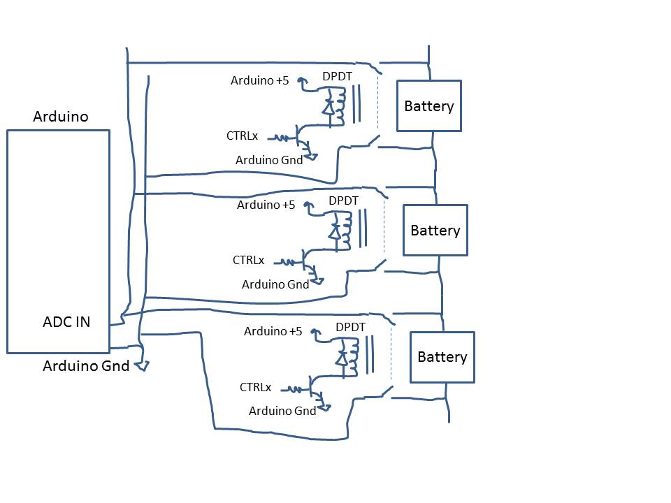
For 24 cells you need e.g. 48 relays, to connect both wires of a DVM or ADC to the + and - of each cell.
48 relays?
Sorry, this is only my second project for arduino I'll be working on and I have very little technical knowledge, but the project above doesn't state anything about relays, just a couple of resistors for the divider and two wires, one negative one positive.
The simple way is voltage dividers on each tap of the cell string.
Voltage dividers, because the Arduino can only work with voltages <5volt.
The first divider loads (discharges a bit) the first cell. The second (tap) loads the first and the second cell.
The third one loads the first, second and third cell. etc.
You see that the first cell discharges faster, because it has to supply all 24 voltage dividers.
There are ICs that can switch taps on/off as needed (74HC4067).
Don't know if there are high voltage ones (60volt).
Resolution goes down with the ratio of the voltage divider, so the measurement of the "top" cell is the least accurate.
As said, you can only measure "tap voltage" this way, so you have to calculate cell voltages (more inaccuracy).
An other way is using small relays to connect each cell in turn to Arduino ground and one analogue input.
Much like you already do now with your DMM. Move TWO terminals to another cell.
Also available in chip form, but more expensive than 24 DPDT miniature relays, and made of unubtanium.
You are right, 24 DPST relays are sufficient, one for each cell. I had SPST relays in mind.
And take care that the Arduino Gnd is not otherwise connected to the battery, neither directly nor through power supply, USB or some other connected device.
I have been playing around with something similar to this but only either 4 or 8 batteries that are wired in series. My testing consists of 2 quad op-amps for 8 batteries set up in a differential mode to read the individual battery voltage, this means I don't have to subtract battery 1 from battery 2. I got the idea from another thread where some one posted it about a battery balancer.
This seems to be working ok some people say use relays but I found it easier with the op-amp. At the moment I'm only testing with 4 batteries and using an 18bit adc chip, but thinking of looking at a multiplex method.
I'm out in a bit can post my drawing if required
Hi,
I posted this basic schematic in another thread for indication of how switch cap measurement could be used.
To select relays you could use a port expander chip to save on controller I/O.
A shift register of the TPIC family can switch eight relays directly (no other parts needed).
You can daisy-chain as many as you like. The whole chain only uses three Arduino pins.
https://forum.arduino.cc/index.php?topic=92074.45
Post#49 has a picture of an 8-cell flying cap volt meter I once designed.
Three boards can be stacked to make a 24-cell flying cap voltmeter.
Diagrams and code are also somewhere in these posts.
Leo..
leo yeah that's the one. I can see you used a 4051 I may do that way so I can use the MCP3426 16bit adc been studying nick's example of the 4051 just playing around with that rather than the 10bit analogue read bit just trying to figure it out.
Tom that looks interesting idea