[W5500] UDP message not received & Ethernet shield not detected on Arduino Mega

Hello everyone,

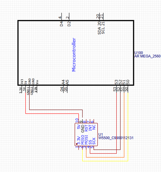
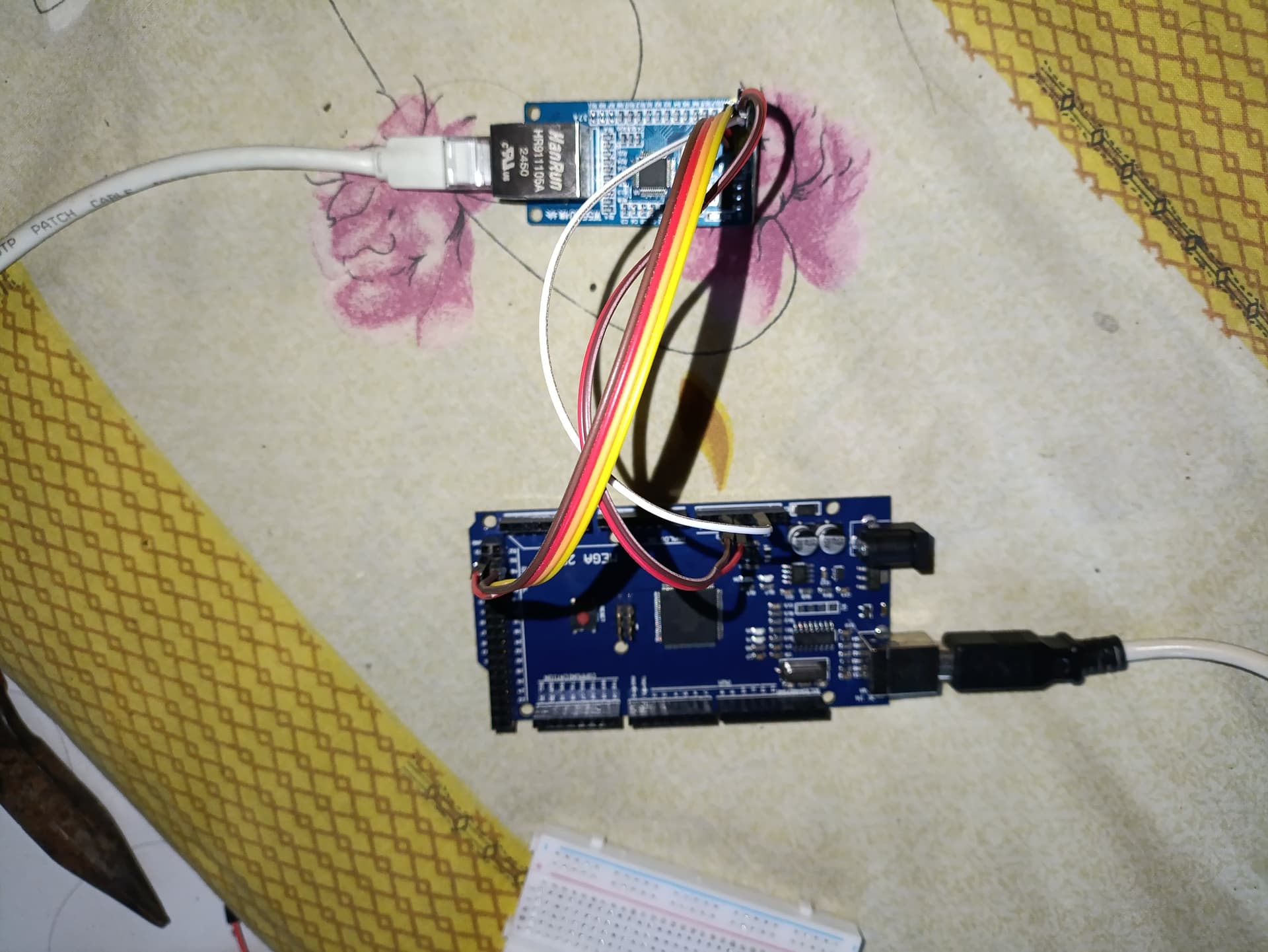
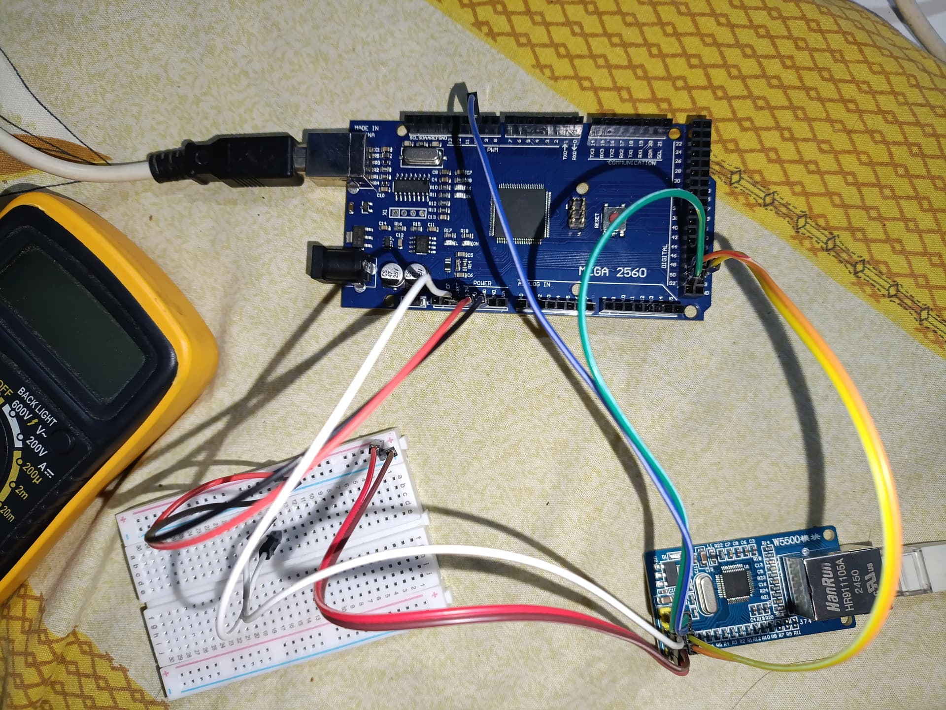
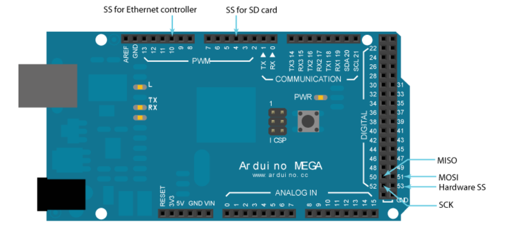
I'm trying to create a UDP message sender using my Arduino Mega with a W5500 Ethernet module. I wired the W5500 to the Mega as shown in the diagram below:
I use the MISO, MOSI, SCK and Hardware SS

Here's the code I'm using to send a UDP message to my computer:

#include <SPI.h>
#include <Ethernet.h>
#include <EthernetUdp.h>

// MAC dan IP statis Arduino
byte mac[] = { 0xDE, 0xAD, 0xBE, 0xEF, 0xFE, 0xED };
IPAddress ip(192, 168, 2, 177); // IP Arduino
// IPAddress subnet(255, 255, 255, 0);

EthernetUDP Udp;
unsigned int localPort = 8888;  // Port UDP lokal Arduino

void setup() {
  Serial.begin(9600);
  while (!Serial) {}

  Serial.println("Starting Ethernet...");
  Ethernet.begin(mac, ip);
  delay(1000);

  Serial.println("Starting UDP...");
  Udp.begin(localPort);

  Serial.println("Setup complete.");
}

void loop() {
  IPAddress remoteIp(192, 168, 2, 100);
  unsigned int remotePort = 9999;

  Udp.beginPacket(remoteIp, remotePort);
  Udp.write("Hello from Arduino");
  Udp.endPacket();

  Serial.println("Message sent.");

  delay(1000); // Kirim tiap 1 detik
}

The serial monitor shows "Message sent.", but my computer doesn't receive anything.
I've already set a static IP on both devices and disabled WiFi. I also monitored port 8888 using Wireshark, but no packets are detected.

To verify the hardware, I tested it with this sketch:

#include <SPI.h>
#include <Ethernet.h>

byte mac[] = {0xDE, 0xAD, 0xBE, 0xEF, 0xFE, 0xED};
IPAddress ip(192, 168, 2, 177);

void setup() {
  Serial.begin(9600);
  while (!Serial) {
  }

  Ethernet.begin(mac, ip);

  if (Ethernet.hardwareStatus() == EthernetNoHardware) {
    Serial.println("Ethernet shield was not found.");
  }
  else if (Ethernet.hardwareStatus() == EthernetW5100) {
    Serial.println("W5100 Ethernet controller detected.");
  }
  else if (Ethernet.hardwareStatus() == EthernetW5200) {
    Serial.println("W5200 Ethernet controller detected.");
  }
  else if (Ethernet.hardwareStatus() == EthernetW5500) {
    Serial.println("W5500 Ethernet controller detected.");
  }
}

void loop () {}

but somehow the output is
09:25:17.202 -> Ethernet shield was not found.

any idea what happen ? i also try connected it with RJ cross and Straight but still nothing happen

do you have any SD card in your ethernet shield? If so remove it.

what you can try is to add following lines at the top of setup() - before the Ethernet.begin()

  pinMode(10, OUTPUT);                           // set ethernet CS as output
  pinMode(53, OUTPUT);                           // set ATMega-2560, pin 53 hardware cs pin output, even if un-used. https://www.arduino.cc/en/Reference/Ethernet
  delay(1000);

start with the Hardware test sketch. You must make it work before proceed with your UDP example.

i am not uusing the Ethernet Shield — I’m using the w5500 module
like in the image below. So there is no SD card or SD CS pin involved:

void setup() {
  pinMode(10, OUTPUT);                           // set ethernet CS as output
  pinMode(53, OUTPUT);                           // set ATMega-2560, pin 53 hardware cs pin output, even if un-used. https://www.arduino.cc/en/Reference/Ethernet
  delay(1000);
  // Open serial communications and wait for port to open:
  Serial.begin(9600);
  while (!Serial) {
    ; // wait for serial port to connect. Needed for native USB port only
  }

  Ethernet.begin(mac, ip);

However, I’m still getting the message:
15:53:43.871 -> Ethernet shield was not found.
I double-checked the wiring as per the datasheet, but it still doesn’t work. I'm not sure what’s wrong here. Could it be something with the SPI communication or wiring?
I’m connecting the W5500 module directly to the computer via RJ45, and I’m using a static IP

however you MUST connect a CS Pin as the W5500 is a SPI device.

Show us YOUR wiring diagram AND real pictures so we can check each wire on the picture.

Using a correct wired W5100 with CS on Pin 10 I get with your testsketch:

11:01:02.294 -> W5100 Ethernet controller detected.

the wiring is something like this (minus reset because i cant find the reset pin in EasyEda)

Here are real photos of my current setup:

Top view of the wiring:

W5500 module close-up:

Arduino Mega connection:

connect the Ethernet CS Pin to Pin 10 of the AVR and retry.
(Your pictures are of poor quality. I can't check where each cable goes. You could have used at least different wire colours. This not only helps us - but also yourself).
If I were you I would use RED only for power cables and Black only for GND.

Sorry about the image
but i change as you suggested

red = 5v
white = RST
Brown/Black = GND
Orange = MISO = pin 50
Yellow = MOSI = pin 51
Green = SCK = pin 52
Bllue = CS = pin 10

this is the image

the output is still like this, what do you think the problem ?
17:03:01.533 -> Ethernet shield was not found.

what's about the LEDs on the breakout board?
is power indicating that the boards is powered?
the state of the two leds of the RJ45 socket?