Is that how things were before my modification?
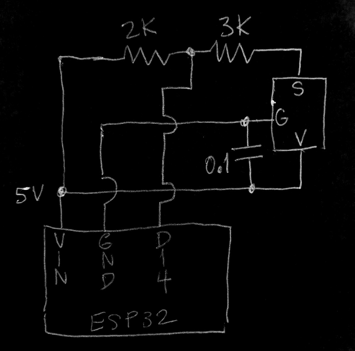
(The FM output was pulled-up before, as it is still, the difference being the mod has a tap at approx. 3V)
Is that how things were before my modification?
(The FM output was pulled-up before, as it is still, the difference being the mod has a tap at approx. 3V)
Do you mean whether this problem with Wi-Fi appeared before? No, everything was fine before adding those resistors.
And that is all that has changed?
Other than the "3V tap" it's the same.
I hate fritzing because I cannot correct it (without downloading fritzing which I shall not do, or doing a lot of fuss and bother with ms_paint).
Does fritzing make a fritzy-pic from a schematic or only the other way round?
There are discrepancies between the fritzy-pic and the attempted schematic.
Yes, if I change back schematics, everything works (still, pulses are not shown correctly).
Basically I add and move the parts around in the Breadboard section, also Schematic and PCB gets generated automatically as I do it. Then, I export the image.
Sorry, I think some wires were behind one another and it might looked like it was incorrect, please check the one below (I've repositioned them so it would look more like yours). Still, breadboard stays the same and ESP cannot connect to the Wi-Fi.
#define ONE_WIRE_BUS 4
Is that for the flowmeter ? (4 vs 14)
and then there is
  // Initialize the D2 pin as an output
  pinMode(ONE_WIRE_BUS, INPUT_PULLUP);
  attachInterrupt(digitalPinToInterrupt(ONE_WIRE_BUS), pulseCounter, FALLING);
So ONE_WIRE_BUS is getting pulled up to 3V .
Change to
pinMode(ONE_WIRE_BUS, INPUT);
(Side note that line could be commented entirely as all GPIO are INPUTs by default but someone will need to gig me.)
Can you spin your program where it's not using wifi and just looking at the flowmeter and knocking out numbers to Serial Monitor?
The newly updated code is shown at post #21.
GPIO:
pcnt_config.pulse_gpio_num = GPIO_NUM_14;
It's really complicated for me print data to serial, because my flow meter is already mounted, and my PC is not near it. Basically I am testing whether it connects to Wi-Fi without my sensor attached.
P.S: at your post #45 schematic Then works indeed, I've just checked it.
I don't grok the Post_21 sketch at all.
Then vs Now is baffling.
My assumption, given the 'Then' ckt, it seems the flowmeter output is 'open collector'.
What if you remove the 2.2k ?
From the Now? I think I mentioned it in post #38. It does connect to the Wi-Fi, but I did not check anything about whether the data is correct. If you agree I can remove 2.2K, I will leave this sensor working for a while to check the data correctness or any weird and random deviation of pulses. Thanks.
Ok. yes - I am losing it.
Remove the 2.2k ("R2") and see if Data is good.
(Why not?)
The trouble is in understanding the configuration of the flowmeter output (internal).
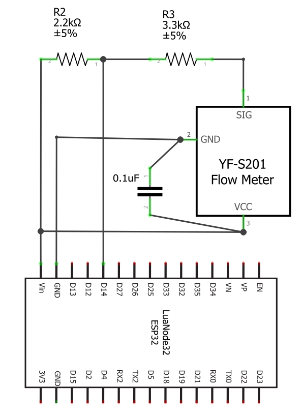
Fixed the divider. Added second capacitor to provide some hardware debounce (limits the max pulse frequency to around 3kHz.
Is the output not 'open collector'?
(And wouldn't R2 and R3 have to be swapped?)
The 4k7 didn't scupper the wifi, but 'voltage-divider style' did.
(I've removed the diagram above to avoid confusion .. thanks)
Oh, if its open collector, then maybe use the 3.3V pin as a pullup?
EDIT:
Just noticed that from here, it says GPIO 14 outputs PWM at boot. GPIO 13, 18, 19 and 21 look good.
@dlloyd
OC or not? I don't know. The original presentation/diagram looked like it was.
The microcontrollerslab article (above Post_26) leads me to suspect that it is not OC. Or something (??) else.
If I had one of these I could find out.
Bench-test before installation (no offense to anyone).
@runaway_pancake, I still received random pulses maybe around from every 20 minutes to an hour, not sure exactly the interval.
@dlloyd, as far as I have tested your provided variation, I did not receive any random pulses. Basically I've tested throughout these last days, and everything seemed fine. Is the schematic and
diagram correct as far as you have you showed?
Schematic:
Breadboard:
Not sure if the last problem with the inaccurate water consumption associates with the schematics, hardware or my code, but the data still seems incorrect (at least no random pulses occur).
The inaccuracy as far as I have collected is:
If I ran my tap fast, it showed me 185 pulses (482 millilitres), in reality it was 500 millilitres.
Lowering the tap speed decreased the pulses to 181 (472 millilitres), in reality it was 500.
Very low speed resulted in 135 pulses (353), in reality it was 500.
Flushing the toilet resulted in 3651 pulses (3.651 litres), in reality it was 3.34 litres.
I've modified my waterCounterTask, so it would get the pulses every minute, apply the formula, and post the data, still no luck. Could this be just the poor quality of the sensor? Thanks.
void waterCounterTask(void *pvParameters)
{
    pcnt_counter_pause(PCNT_UNIT_0);
    pcnt_counter_clear(PCNT_UNIT_0);
    pcnt_counter_resume(PCNT_UNIT_0);

    // Delay
    vTaskDelay(waterCountReadFrequency);

    TickType_t xLastWakeTime = xTaskGetTickCount();

    for (;;)
    {
        pcnt_counter_pause(PCNT_UNIT_0);
        pcnt_get_counter_value(PCNT_UNIT_0, &pulseCount);
        pcnt_counter_clear(PCNT_UNIT_0);
        pcnt_counter_resume(PCNT_UNIT_0);

        // Calculate flow in millilitres
        flowMillilitres = pulseCount / calibrationFactor / 60 * 1000;

        // Finally post water used
        post(flowMillilitres);

        // Delay
        xLastWakeTime = xTaskGetTickCount();

        // 60 seconds delay
        vTaskDelayUntil(&xLastWakeTime, waterCountReadFrequency);
    }

    vTaskDelete(NULL);
}
It seems these tests are based on 1/2 liter volume, but it isn't clear what the flowrate is ... just "fast", "decreased" and "low speed".
In one of the links shown earlier, it mentions in the specification that the flowrate range is 0.3 to 10 L/min. I suspect your last test is below 0.3L/min flowrate.
If the results at different flowrates are consistent, perhaps you could plot an error curve, then use a formula for the calibration factor to correct the error, or use different calibration factors, each covering a smaller rage of flow.
The diagram looks OK, just not sure if the sensor outputs 5V pulses or if its open-collector type. Could check with a multimeter or scope.
Earlier, there must have been some spurious switching noise ... the second 0.1uF capacitor is filtering this.
My model is YF-B5, the flowrate range is 1-30 L/min. The tests I've done were in the range of that - my "very low speed" filled a cup of 500 millilitres in like 10 seconds, fastest one in 3 s.
Well, as I have given my results above, they are indeed not consistent at different flowrates - different water running speed resulted in different pulse outcome (counting throughout each minute). Not only that, but also I was in the given range of 1-30L. Or maybe I did not understand what you meant with inconsistency at different flowrates. If yes, could you please elaborate on that or is there anything else I could do regarding this issue?
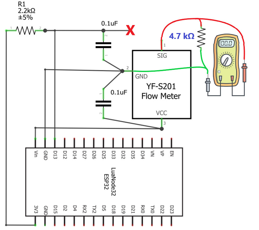
For this I would need to connect red multimeter's wire to yellow wire of the water flow meter (looking from the diagram), black to ground? And If I power my ESP and multimeter always reads 5V, it's output voltage, and if it shows 3.3V when wheel is spinning and 0V when not, it's open collector?
Thanks for your input and help.
Yes. Also:
disconnect yellow wire from esp32.
connect a pulldown resistor (1K to 10K) from yellow wire to GND.
If you continuously read 0V with the flow meter running, then its open-collector.
if you read 0-5-0-5 ... or varying voltage with, then it has an active push-pull output.
I meant if the tests are repeatable when run again at the same flowrates.
Here's a library and some info on how they did calibration.
I put one end of 4.7k resistor in breadboard where yellow wire comes in of the water flow meter, the other end - in GND line. Touching both sides of the resistor with multimeter when the water was not running resulted in 1.61V (constant), when running - it varied between 0V to 1V (sometimes reaching 1.3V). Could this be correct? Why it is not showing 5V? And does this mean it's push-pull? How does that change the schematics? Thanks.
Thanks for this link, I really appreciate it. I will try to apply this myself. I will post the results later on and whether this solved my issue. Thanks.