The attached pics show my wiring setup and example code for reading a digital input.
Is there any glaring errors to why the pushbutton input refuses to change state? Wiring has been triple checked and ohmed out. The LED actually works by a stroke of unbelievably good fortune. lol...
You are using delay() which means as long as the delay(1000) is executed nothing else happens.
you have to press down the button looong enough to make the code execute the line
buttonState = digitalRead(buttonPin);
again.
If you press it short in 99% of all cases you will miss that exact millisecond when this line
buttonState = digitalRead(buttonPin);
is executed. Your code with comment on delay(1000)
const int buttonPin = D2;
const int ledPin = D7;

int buttonState = 0;

void setup() {

  pinMode(ledPin, OUTPUT);

  pinMode(buttonPin, INPUT);
}

void loop() {

  Serial.begin(115200);

  buttonState = digitalRead(buttonPin);
  Serial.print(buttonState);
  Serial.println();
  delay(1000); // one second long no button-state detection

  if (buttonState == HIGH) {
    digitalWrite(ledPin, HIGH);
  }
  else {
    digitalWrite(ledPin, LOW);
  }
}
non-blocking timing
If you use non-blocking timing your code becomes reactive to the button-presses all the time
The following code demonstrate two things:
how to use functions to structure your code into senseful sub-units.
Though two or three lines of code are not that much.
But it is easier to see what the principle is.
non-blocking timing
You want to see what state your button is at detecting a HIGH = 1 or detecting a LOW = 0
and print this only once per second to the serial monitor
const int buttonPin = D2;
const int ledPin = D7;

int buttonState = 0;

unsigned long MyTestTimer = 0; // Timer-variables MUST be of type unsigned long
const byte    OnBoard_LED = 2;

unsigned long myDemoCounter = 0;

void setup() {
  Serial.begin(115200);
  Serial.println("Setup-Start");
  pinMode(ledPin, OUTPUT);
  pinMode(buttonPin, INPUT);
}


void loop() {
  BlinkHeartBeatLED(OnBoard_LED, 250); // make onboard LED blink
  myDemoCounter++; // demo counter to show how fast loop is looping
  buttonState = digitalRead(buttonPin);

  if (buttonState == HIGH) {
    digitalWrite(ledPin, HIGH);
  }
  else {
    digitalWrite(ledPin, LOW);
  }

  // NON-blocking timing based on function millis()
  // check if 1005 milliseconds have passed by
  if ( TimePeriodIsOver(MyTestTimer, 1005) ) {
    // when REALLY 1005 milliseconds have passed by
    // automatically update variable "MyTestTimer" inside the function TimePeriodIsOver
    printButtonState();
    printCounter();
  }
}


void printButtonState() {
  Serial.print("buttonState is:");
  Serial.println(buttonState);
}


void printCounter() {
  Serial.print("counter is at:");
  Serial.println(myDemoCounter);
}


// easy to use helper-function for non-blocking timing
boolean TimePeriodIsOver (unsigned long &startOfPeriod, unsigned long TimePeriod) {
  unsigned long currentMillis  = millis();
  if ( currentMillis - startOfPeriod >= TimePeriod ) {
    // more time than TimePeriod has elapsed since last time if-condition was true
    startOfPeriod = currentMillis; // a new period starts right here so set new starttime
    return true;
  }
  else return false;            // actual TimePeriod is NOT yet over
}


void BlinkHeartBeatLED(int IO_Pin, int BlinkPeriod) {
  static unsigned long MyBlinkTimer;
  pinMode(IO_Pin, OUTPUT);

  if ( TimePeriodIsOver(MyBlinkTimer, BlinkPeriod) ) {
    digitalWrite(IO_Pin, !digitalRead(IO_Pin) );
  }
}
Not according to reference info I found, including:;
I went ahead and tried D4 as well already. No change in problem.
edit - whoops...I misunderstood your concern.
The "D3" on the button shield just mimics the Memos D1 board silk screening. The button shield actually has 16 pins w/ identical silk screening to the Wemos D1 even though only four pins are wired to the switch.
I pressed the button continuously for 5-10 secs with no change on the serial monitor output.
The delay just slows down the display output to the serial screen.
Using the same wiring configuration and code presented in Post #1 I tested every input on the processor. The results are odd:
Input State seen on serial monitor
D0 = 0
D1 = 1
D2 = 0
D3 = 1
D4 = 1
D5 = 1
D6 = 1
D7 not tested; LED wired to it
D8 =
D8 is the only input I could see change state as a function of the switch opening/closing.
Why is this I wonder? I have never worked with a Wemos D1 mini before but everything
else in the code and wiring so far has checked out. Including monitoring a varying voltage input through the one and only AI input and writing/erasing/appending a SPIFFS file.
There has to be more to this story that I am yet to understand.
even a 4 inch long wire acts as antenna that is catching up electromagnetic noise
wich can make the IO-pin switch randomly between LOW and HIGH
repeat your test with
pinMode(Pin_Nr,INPUT_PULLUP);
with connecting the button between IO-pin and ground
Did you read the RNT-Tutorial linked above ?
Some IO-pins have pullup resistors some have pulldown
Unfortunately I would have to de-solder it from the breadboard to be sure but this
link shows a pic of the back:
To be clear I did not use the button shield while testing all the dig inputs. I used a prototype breadboard with jumpers to recreate the wiring w/ a 10k resistor and switch.
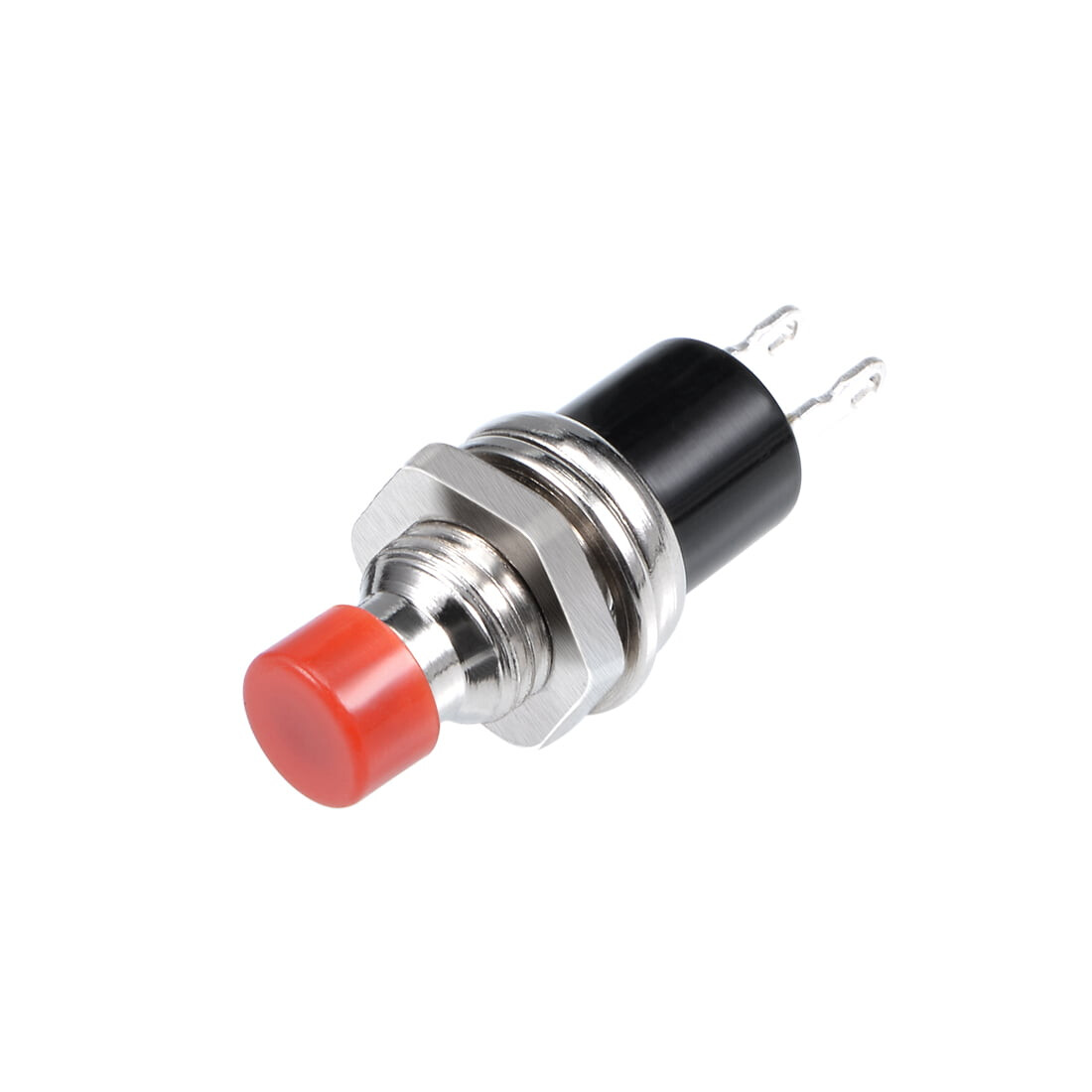
If it is one of these for pin buttons always two of them are connected to each other permanently
Do you have a digital multimeter (DMM) ?
Did you test your buttons with the DMM?
Did you measure the voltage-levels with the DMM while the button is connected to the IO-pin?
Do the voltage-levels of the DMM suit to the logic level that gets printed in the serial monitor?
If you don't have a DMM. Now you really know you need one
I did measure the 3.3v sourcing the one side of the button shield switch and read the 3 v across the 10k resistor while the switch was made.
The RNT tutorial chart shows D8 as an input which is "pulled to GND" and was the only input that worked with the switch during my testing. If the other inputs are "pulled up" I wonder what is the correct wiring methodology for using them?
I did change the code as you suggested by modifying the pinMode:
pinMode(Pin_Nr, INPUT_PULLUP)
pinMode(Pin_Nr, INPUT)
and used a switch between GND and the input. There was no change. I also tried each of these
while incorporating the 10k resistor and the 3.3v pin.
So far the only method that has worked repeatedly is using D8 w/ a 10k resistor and sourcing the 3.3v pin.
I am going to mark this thread SOLVED as I have D8 working through the button shield now.
Until I find out how the other "pulled up" inputs are supposed to be correctly wired I will continue on using just D8, as my sketch only requires one dig input.
I did use the 10k resistor w/ one leg tied to GND an the other leg tied to the switch pin and the D8 input; 3.3v pin feeds the other side of the switch.
A switch is not a device like a sensor that needs GND and +3,3V
If you use pinmode INPUT_PULLUP connecting the one pin of the switch to the IO-pin and connecting the other pin of the switch to GND is totally sufficient. If you start adding another resistor or connecting it to +3.3V you are disturbing the original circuit which only needs the pure mechanical switch.
A "switch" that requires to have an extra GND and an extra +3.3V connection is no longer a simple switch.
You can read about the different ways how to connect simple switches here
Thanks for the input and links. Admittedly I do not clearly understand the distinctions between
input_pullup and input_pulldown. I need to read up on the subject and will reference your information.
The button shield is working and reliable using the 10k resistor on D8 so I am content for now.
You could have a pure analog-hardware-backup by using a shottky-diode tp prevent current flowing into the battery-package.
If your DC-DC-converter is running on 5V connected to V-in and your battery-package is running at 4.2V connected to Vin over a shottky-diode that prevents current flowing from Vin-pin into the battery this should switch within nanoseconds.
If I remember right You have not yet told that you are using a battery.
Id this a chargeable battery? If yes dO you want to charge this battery whenever the DC-DC-converter supplies the device?
That is correct. I did not consider it related to the dig input issue.
I just realized I posted my update to the wrong thread. The other thread was about the processor halting when the converter switched over. I will correct that.