Hi, I am trying to figure out what gauge wire I should use on my circuit and where to put them.
I currently only have the 22-gauge wire that comes with the Arduino kit. I think this will be fine for all the wires except the 5v and ground wire that connects the PSU and the servo driver. The servos are MG995 so that max current draw of each is 1.5 amps at stall. This means there should be no more than 9 amps being drawn.
!! I now realized that the image says that the power supply is 12w when it should say 12 amps. !!
In my mind the amperage going through the red and black wires between the servos and the driver could be up to 1.5 amps because that is the stall current of the servos, exceeding the max amps of the wire. But I could be wrong
Besides initial startup, how many servos might be moving at the same time? If, on startup, ALL servos will try to go to the default position (90°) at the same time unless you put a delay between each attach.
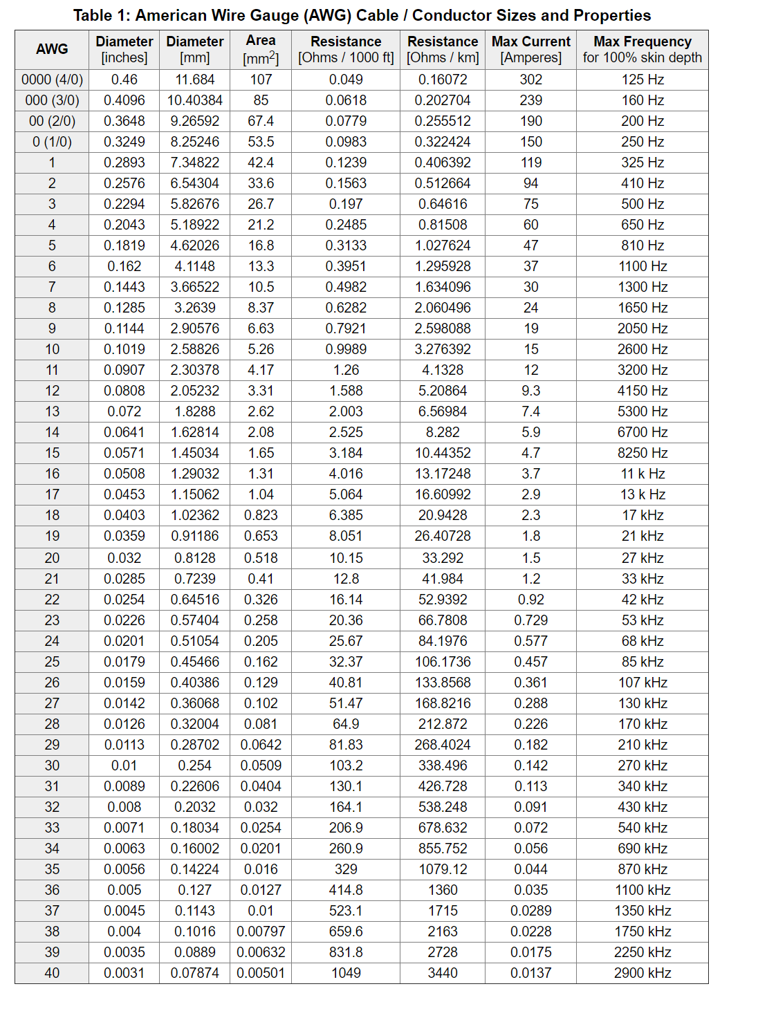
ya that is what I dont get. I believe the MG995 have wires that are 22g which are rated for up to 0.92 current yet the stall current ranges from 1.2-1.5.
I think you are missing the whole point about what a wire rating means. The thicker the wire, the lower resistance per unit length. The resistance results in two things, voltage drop at the other end of the wire and how much the wire will heat up.
The heat difference between 0.9 Amps and 1.5 Amps is hardly here nor there and the voltage drop especially for an initial surge current is also irrelevant. If you were to get wire rated exactly at 1A then a brief surge at 1.5 Amps would not do any harm.
Wire ratings are not fuse ratings where the wire has to heat up and melt at a specific current.
And unless the servos are in frequent motion, the only thing you will notice with inadequate wire rating, is that they will not respond quite as promptly as they should, particularly when many are moving simultaneously.
But how would you be able know the difference between what they do and what they "should"?
Ok great! This is very helpful! I got some 12-gauge wire today and hooked it up between the power supply and the servo driver. This seems like overkill now with the information that you gave me, but I don't think having 22 vs 12 gauge will cause any noticeable difference in performance.